EasyManua.ls Logo

Siemens SSE161.05U User Manual

Siemens SSE161.05U
14 pages
To Next Page IconTo Next Page
Page #1 background imageLoading...
Page #1 background image
Electromotoric actuator
SSE161.05U, SSF161.05U
For 2-way & 3-way 599 Series Zone Valves
Operating voltage AC/DC 24 V, positioning signal DC 0...10 V
Self-calibrating to the valve stroke
Direct mounting with coupling nut, no tools required
Manual override
Position and actuator motion indication (LED)
Positioning force 45 lbf (200 N)
Parallel operation of multiple actuators possible
3-pin terminal block
A6V12681514_enUS_b
Smart Infrastructure
06/15/2023
Question and Answer IconNeed help?

Do you have a question about the Siemens SSE161.05U and is the answer not in the manual?

Siemens SSE161.05U Specifications

General IconGeneral
BrandSiemens
ModelSSE161.05U
CategoryController
LanguageEnglish

Summary

Use Cases and Applications

Technical Design and Functionality

DC 0-10V Control Signal Operation

Details actuator response to DC 0-10V signals, including stroke and valve positioning.

LED Status Indicators

Explains the meaning of various LED patterns for status, calibration, and errors.

Product Specifications Overview

Ordering Information

Delivery Options

Equipment Compatibility

Compatible Valve Series

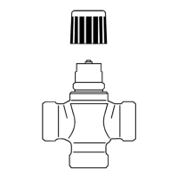
Lists 2-way and 3-way 599 Series Zone Valves that can be combined with the actuators.

Product Documentation References

Installation and Compliance Documents

References for installation, standards, directives, and environmental compatibility documents.

Important Notes and Guidance

Engineering and Safety Notes

Key considerations for electrical connections, national safety regulations, and permissible temperatures.

Mounting Instructions

Actuator Orientation

Commissioning Procedures

Self-Calibration Process

Manual Actuator Operation

Manual Stem Adjustment

Wiring and Cabling

Maintenance, Repair, and Disposal

Warranty Policy

Open Source Software Information

Detailed Technical Data

Power Supply and Signal Input

Covers operating voltage, frequency, power consumption, control signal, and input impedance.

Operating and Performance Data

Includes running speed, positioning force, stroke, and permissible medium temperature.

Electrical Connections and Mounting

Details signal line length, wire specifications, cable diameter, and valve connection type.

Compliance and Protection Standards

Lists conformity declarations (CE, RCM, UKCA) and protection class ratings.

Standards, Regulations, and Environment

Material Composition and Weight

Connection Diagrams and Terminals

Terminal Identification

Defines the terminals and their functions for actuator wiring.

Wiring Schematics

Provides electrical connection diagrams for integrating the actuator with a controller.

Physical Dimensions and Revisions

Related product manuals