TX-I/O Quick Start
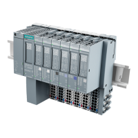
P1 Bus Interface Module, TX-I/O Power Supply, and
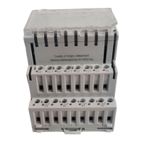
Bus Connection Module
24VRUN
FLT
COM
24V
CS CD
S -
+
24V
T
1
2
3
5
4
LAN
Connection
+ 24 Vdc
Data
24 Vac In
Common
TXIO0029R1
P1 Bus Interface Module (P1 BIM) TXB1.P1
Power and Communication Connections
Symbol Device Description
All 24 Vac IN (from transformer)
⊥
All Common Ground
CS
All (feed-thru on TX-I/O Power Supply and Bus
Connection Module)
24 Vdc Communication Supply
(24 Vdc)
CD
All (feed-thru on TX-I/O Power Supply and Bus
Connection Module)
Communication Data (Signal)
S - +
P1 BIM LAN connection
Extending Communication
If an installation requires more than one DIN rail, connect the Communication
Supply (CS) and Communication Data (CD) terminals from the P1 BIM to the
same terminals on the first device of every additional DIN rail (a TX-I/O Power
Supply or Bus Connection Module). TX-I/O Power Supplies and Bus Connection
Modules include a second set of CS and CD contacts to simplify connection of
additional DIN rails. Ensure that the system neutral is installed.
NOTE:
Maximum extension of the TX-I/O bus is 50 meters total for all devices.
12 Siemens Building Technologies, Inc

 Loading...


