VRD4 Series Double Valves Technical Instructions
Document Number CC1N7649us
September 08, 2016
Siemens AG Building Technologies Division Page 7
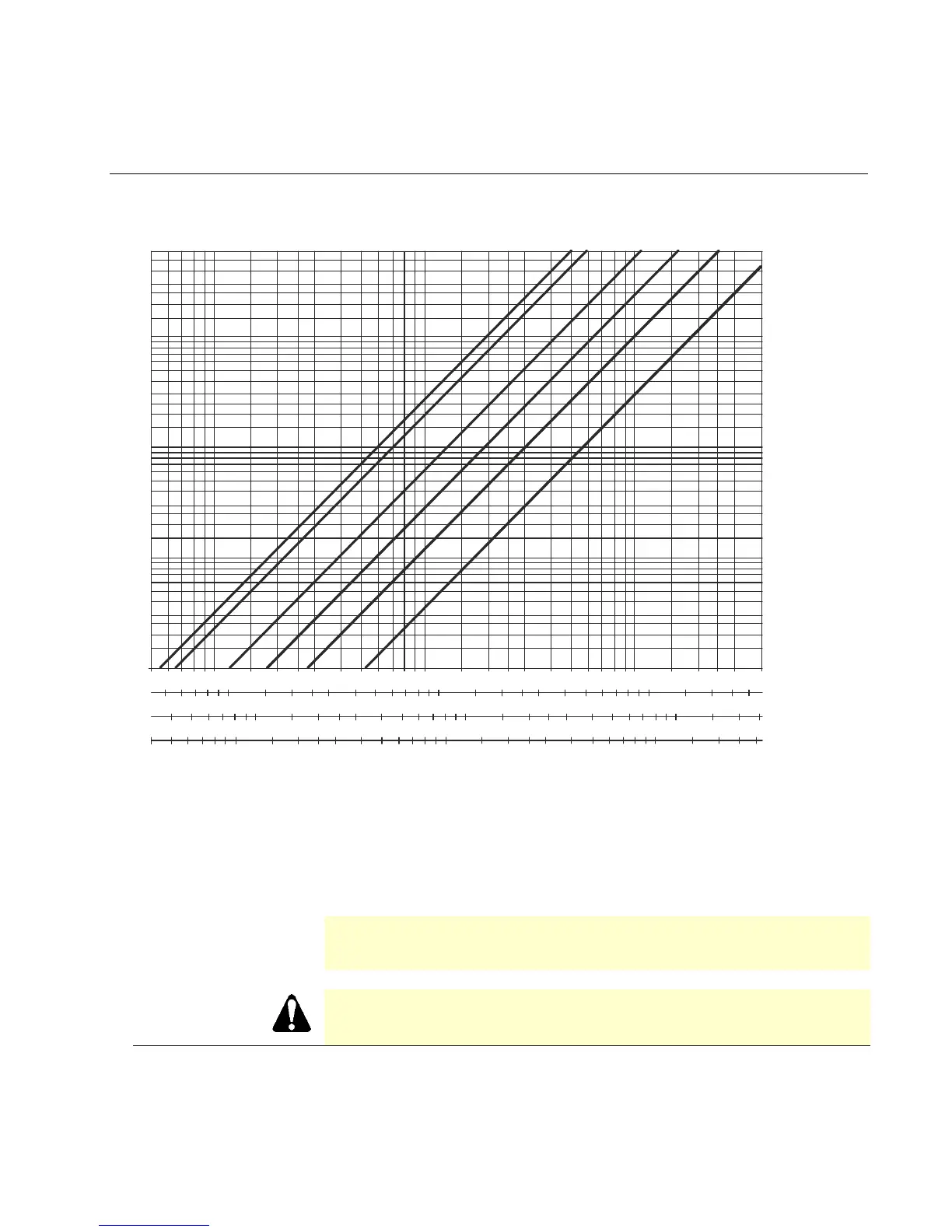
Gas flow charts
1 1/2" (40)
2" (50)
2 1/2" (65)
3" (80)
4" (100)
6" (150)
500
400
300
200
100
70
50
40
30
20
10
7
5
4
3
2
1
0.7
0.5
0.4
0.3
0.2
0.1
Pressure drop (in w.c.)
Natural gas
Digester gas
Propane gas
Air
5 7 1000 2 3 4 5 7 10000 2 3 4 5 7 100000 2 3 4
5 7 1000 2 3 4 5 7 10000 2 3 4 5 7 100000 2 3
4 5 7 1000 2 3 4 5 7 10000 2 3 4 5 7 100000 2
4 5 7 1000 2 3 4 5 7 10000 2 3 4 5 7 100000 2 3
Flow rate (SCFH)
7649d01us/0614
Figure 2. Sizing double valves
Assumptions:
1) Pressure downstream of valve is atmospheric
2) Maximum gas temperature of 140 °F
3) Valve in fully open position
NOTE:
Pressure drop is total drop across both valves when using SKPx5…
actuator, with or without an AGA66.
CAUTION:
Do not oversize valves equipped with regulating actuators SKP2…, SKP5… or SKP7…
Oversizing may limit turndown and could cause oscillations.
 Loading...