Description of the device
2.1 Device views
SCALANCE X-200
16 Operating Instructions, 03/2015, C79000-G8976-C284-06
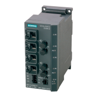
Device view based on the example of an X202-2P IRT PRO
The following figure describes the individual components of a PRO version of an IE switch X-
200.
Electrical attachments to Industrial Ethernet
LEDs for electrical connectors
LEDs for optical connectors with diagnostics
LEDs
L: Power LED, power supply
RM:
– green = redundancy manager
– yellow = standby indicator
Optical attachments to Industrial Ethernet
Connector for the power supply (supplied with
L1, additionally looped through to L2)
Connector for signaling contact
Power supply for further devices (looped
through from L1 to L2)
(on rear of device, not shown in figure): Slot for
the C-PLUG and SET button
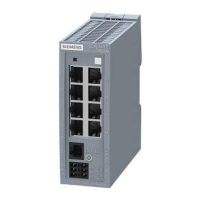
Device view based on the example of an XF204
The following figure describes the individual components of an IE switch X-200, flat design.
L: Power LED, power supply
Attachments to Industrial Ethernet
Connector for power supply
Connector for signaling contact
(behind the connectors, not shown in figure:)
SET button
(on side of device, not shown in figure:) Slot for
C-PLUG
LEDs for attachments to Industrial Ethernet
 Loading...