SCALANCE X-200
Operating Instructions, 03/2015, C79000-G8976-C284-06
15
Description of the device
Device views
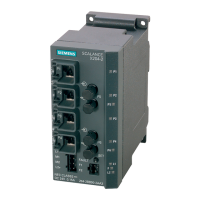
Device view based on the example of an X204-2TS
The following figure describes the individual components of an IE switch X200.
LEDs for attachments to Industrial Ethernet
L: Power LED, power supply
RM: Redundancy manager or standby
Connector for signaling contact
Connector for power supply
Optical attachment to Industrial Ethernet
Electrical attachment to Industrial Ethernet
(on rear of device, not shown in figure:) Slot for C
 Loading...