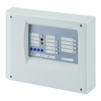
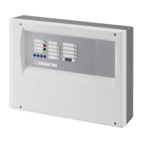
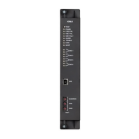
Overview
17
Building Technologies A6V10257473_e_en_--
Fire Safety 2015-03-04
PCB terminal blocks
X1 Plug-in block 6 points
(1.5 mm
2
max.)
1-2 (–) / 5-6 (+) 24V power supply
3-4 (+) Power supply monitoring
X5 Plug-in block 4 points
(2.5 mm
2
max.)
1 (+) / 2 (–) Monitored output 5
3 (+) / 4 (–) 24V use output
X6 Plug-in block 4 points
(2.5 mm
2
max.)
1 (+) / 2 (–) Monitored output 3 (control polarities, reversed in standby)
3 (+) / 4 (–) Monitored output 4
X7 Plug-in block 4 points
(2.5 mm
2
max.)
1 (+) / 2 (–) Monitored output 1 (control polarities, reversed in standby)
3 (+) / 4 (–) Monitored output 2 (control polarities, reversed in standby)
X9 Plug-in block 8 points
(1.5 mm
2
max.)
1 (+) / 2 (–) Monitored input 1
3 (+) / 4 (–) Monitored input 2
5 (+) / 6 (–) Monitored input 3
7 (+) / 8 (–) Monitored input 4
X10 Plug-in block 8 points
(1.5 mm
2
max.)
1 (+) / 2 (–) Fire detectors zone 1
3 (+) / 4 (–) Fire detectors zone 2
5 (+) / 6 (–) Fire detectors zone 3
7 (+) / 8 (–) Extinguishing manual control
X11 Plug-in block 10 points
(1.5 mm
2
max.)
1 / 2 Potential-free contact relay 1 (NO or NC)
3 / 4 Potential-free contact relay 2 (NO or NC)
5 / 6 Potential-free contact relay 3 (NO or NC)
7 / 8 Potential-free contact relay 4 (NO or NC)
9 / 10 Potential-free contact relay 5 (NO or NC)
X12 Plug-in block 10 points
(1.5 mm
2
max.)
1 … 8 (–) Logical outputs 1 to 8
9 (–) / 10 (+) Repeater display / Repeater terminal RTNet connection
X21 Jack 2.5 mm — Maintenance PC
X27 Plug-in block 4 points
(1.5 mm
2
max.)
1 (+) Reset
2 … 4 (+) Unmonitored inputs 2 to 4
X28 Faston 5.3 mm (+) To positive of battery (to provide “Total loss of power supply”
function (see note 1)
X20 (*) Flat cable 26 points — Connection for multi-sector module XCA1030
X35 Terminal 12 points — Connection for 4 digits display
X23, 24 Not used — —
(*) on welding side
Note 1: The XC10 provides the EN54-2 option with requirement 8.4 called “Total loss of power”. This option when selected activates the
system fault LED and the buzzer continuously, for at least 1 hour after a low discharge battery disconnection. The option can be
selected by wiring the +BAT terminal to the positive voltage of batteries (use of remaining power after battery disconnection).

 Loading...


