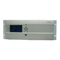
Description of device terminal
5 Time synchronization
Setting description of dial switch: (ON: corresponding position i s 1,
otherwise, the corresponding position is 0)
The dial switch J4 shall set the address of time synchronization module with a
range of 0x00-0x0f (see table 5). To distinguish it with the address of other
module, the 0x0c address is allocated for time synchronization module.
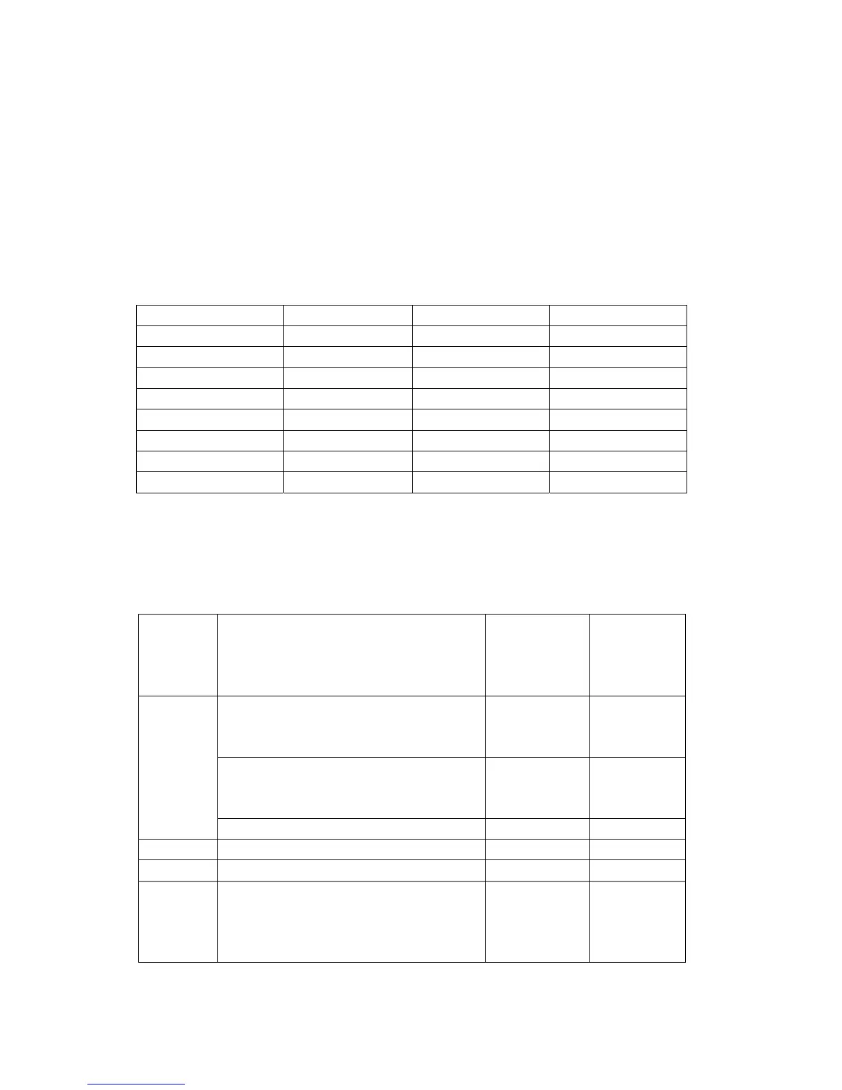
Table 5 Address setting range of dial switch J4
b4 b3 b2 b1 module address b4 b3 b2 b1 module address
0 0 0 0 0x00 1 0 0 0 0x08
0 0 0 1 0x01 1 0 0 1 0x09
0 0 1 0 0x02 1 0 1 0 0x0a
0 0 1 1 0x03 1 0 1 1 0x0b
0 1 0 0 0x04 1 1 0 0 0x0c
0 1 0 1 0x05 1 1 0 1 0x0d
0 1 1 0 0x06 1 1 1 0 0x0e
0 1 1 1 0x07 1 1 1 1 0x0f
See table 6 for the specific setting of dial switch J12 (b1-b4: serial port
protocol type; b5-b8: B code).
Table 6 Address setting range of dial switch J12
Time
synchroniz
ation
method
b8 b7 b6 b5 b4 b3 b2 b1 Synchronous
clock type
Remarks
Serial port
+ pulse
time
synchroniz
ation mode
0 0 0 0 0 0 0 1 Serial port
connecting
SN-1
Sifang
0 0 0 0 0 0 1 0 Serial port
connecting
BSS
Wave
electricity
0 0 0 0 0 0 1 1 Reserved
~ Reserved
0 0 0 0 1 1 1 1 Reserved
B code
time
synchroniz
ation mode
1 0 0 0 0 0 0 0 Differential
and level
signal