EasyManua.ls Logo

SIGMATEK CCP 521 - User Manual

SIGMATEK CCP 521
38 pages
Print Icon
To Next Page IconTo Next Page
Loading...
C-DIAS PROCESSOR MODULE CCP 521
15.03.2016 Page 1
C-DIAS Processor Module CCP 521
The CCP 521 processor module runs the control program and
thereby represents an essential component of an automation sys-
tem. The internal DC/DC converter powers all modules on a
C-DIAS module carrier.
The CAN bus, an Ethernet interface or the USB device (Mini USB)
can be used as the online interface.
A 7-segment display and 2 status LEDs provide information on the
actual status of the CPU.
For program updates, the integrated USB Host interface can be
used (USB stick, keyboard). With help from the exchangeable SD
card, the entire control program can be easily exchanged.
The CCP 521 processor module is designed to be mounted in the
control cabinet.
With the integrated VARAN manager, the processor module offers the possibility to con-
struct a high-performance VARAN system to operate for example, decentralized I/O mod-
ules, drive systems or communication modules.
Compatibility
Completely PC-compatible. The CCP 521 works with standard PC BIOS and therefore no
SIGMATEK-specific BIOS is needed; the LASAL operating system in provided.
Question and Answer IconNeed help?

Do you have a question about the SIGMATEK CCP 521 and is the answer not in the manual?

SIGMATEK CCP 521 Specifications

General IconGeneral
BrandSIGMATEK
ModelCCP 521
CategoryComputer Hardware
LanguageEnglish

Summary

CCP 521 Processor Module Introduction

Module Functionality and Interfaces

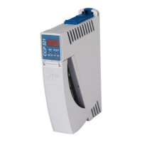
Details the processor module's role, communication options (CAN, Ethernet, USB), and core components.

Status Indicators and Program Management

Covers the 7-segment display, LEDs, and SD card/USB for program updates.

System Integration and Compatibility

Discusses VARAN manager, mounting, and PC compatibility.

Technical Performance Specifications

Core Performance Data

Lists processor, clock frequency, memory, cache, and interface details.

Electrical Requirements and Configuration

Electrical Specifications

Details supply voltage, current consumption, and starting current.

Standard Network Setup

Outlines default Ethernet and CAN bus configuration.

Product Details and Environmental Data

Miscellaneous Product Information

Includes article number, hardware version, and project back-up details.

Environmental Operating Conditions

Specifies storage/operating temperatures, humidity, and EMV stability.

Mechanical Dimensions

Module Physical Size and Layout

Provides diagrams illustrating the physical dimensions of the module.

Connector Layout Diagram

Identification of External Connectors

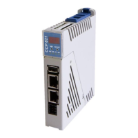
Diagram showing the location and labels for all external interfaces.

Connector Pinout Details

USB and Ethernet Connector Pin Assignments

Details pinouts for USB Device (X1), USB Host (X2), and Ethernet (X3).

Connector Pinout Details

VARAN, CAN-Bus, and Power Connector Pin Assignments

Details pinouts for VARAN (X4), CAN (X5), and Power (X6).

microSD Card Interface and Usage

microSD Card Pinout and Media Recommendations

Covers microSD pinout and advice on compatible storage media.

Connector Wiring and Specifications

Wire Size, Torque, and Connector Types

Details wire gauge, torque, and lists applicable connector types for interfaces.

Status Indicator Functions

Ethernet and VARAN Status LEDs

Explains the meaning of LEDs for Ethernet and VARAN activity and link status.

Control and System Status LEDs

Describes LEDs indicating error and power supply status.

On-Device Display Information

7-Segment Display Capabilities

Describes how the display shows parameters, error codes, and runtime values.

CAN Bus Setup and Configuration

Station Number and Data Transfer Rate

Details setting station numbers and baud rates for CAN bus communication.

Module Configuration Controls

SET and RESET Button Functions

Identifies the physical buttons used for module configuration.

Module Configuration Procedure

Entering, Navigating, and Changing Settings

Step-by-step guide to configuring module parameters like IP address.

Configuration Parameter Examples

CAN Bus and Network Setting Examples

Illustrates display values for CAN station, baud rate, IP, subnet, and gateway.

CAN Bus Termination Requirements

Importance and Method of CAN Termination

Explains why termination is needed and how to apply it using a resistor.

Wiring and Mounting Instructions

Earth Connection Best Practices

Details the critical aspects of establishing a low-ohm earth connection.

Safety, Shielding, and ESD Precautions

Wiring Shielding and Noise Mitigation

Guidelines for effective shielding of communication buses.

ESD Protection and Safe Handling

Procedures to prevent electrostatic discharge damage and ensure safe operation.

Process Flow Diagram

Module Operational Logic Flowchart

Visual representation of the module's boot and run process.

System Boot Checkpoint Analysis

Interpreting Boot Errors and Checkpoints

Guide to understanding system stop points during startup.

Status and Error Messages: Runtime and Pointer Issues

Runtime, Pointer, and Checksum Messages

Details common status messages like RUN RAM, POINTER, CHKSUM.

Status and Error Messages: Hardware and Execution Issues

Hardware, Interruption, and Program Execution Errors

Covers Watchdog, PROM, STOP, and other execution-related errors.

Status and Error Messages: Module and Memory Issues

Program Execution, Module, and Memory Errors

Details errors related to program stops, module compatibility, and memory issues.

Status and Error Messages: DIAS, OS, and Application Issues

DIAS, OS, Loading, and Application Errors

Covers errors related to DIAS modules, OS, loading, and application execution.

Status and Error Messages: VARAN and System Issues

VARAN, System, File, and Runtime Errors

Details errors related to VARAN, system files, and real-time execution.

Status and Error Messages: SRAM and Connection Issues

Runtime, Connection, SRAM, and Initialization Errors

Covers background runtime, connection issues, SRAM behavior, and initialization.

Status and Error Messages: Linking and Syntax Issues

Program Execution, Linking, and Syntax Errors

Details status codes for program execution, linking, and syntax issues.

Status and Error Messages: OS and Power Issues

OS Installation, Power, and Connection Errors

Covers errors related to OS installation, power supply, and connections.

Application Exceptions and Limitations

SRAM and IRQ Routine Restrictions

Warns against data writing during interrupts and its consequences.

SRAM Data Consistency and File System Issues

Discusses potential data loss and file system corruption with SRAM usage.

Unsupported Data Breakpoint Feature

Notes the unavailability of the data breakpoint feature.

SRAM Behavior and Lifespan Considerations

SRAM Data Saving Mechanisms

Explains cyclic writing versus event-based saving for SRAM data.

Impact of SRAM Usage on Media Lifespan

Details how frequent data changes affect microSD card longevity.

VARAN Shielding and Wiring Best Practices

VARAN Bus Shielding Requirements and Cable Types

Recommends shielding for VARAN Ethernet bus and specifies cable types.

Vibration Protection for VARAN Cables

Advises on securing VARAN cables to prevent damage.

VARAN Wiring: Cabinet to External Component

Shielding Between Cabinet and External Component

Illustrates shielding placement for connections outside the control cabinet.

VARAN Wiring: External Component Setup

External Wiring with IP67 Modules

Describes wiring requirements when components are located outside the cabinet.

VARAN Wiring: Internal Cabinet Setup

Shielding for Internal Cabinet Wiring

Details shielding for VARAN bus lines within the control cabinet to mitigate noise.

VARAN Wiring: Noise Source Connection

Shielding for Noise-Generating Component Connections

Advises on shielding placement when connecting power elements to the bus.

VARAN Wiring: Inter-Cabinet Connection

Shielding Between Multiple Control Cabinets

Explains shielding configuration when connecting two control cabinets via VARAN bus.

Related product manuals