Return Value: None
Function Name: void si4455_read_rx_fifo(U8 numBytes, U8* pRxData)
Description: Reads the RX FIFO content from the radio.
Input Parameter(s): numBytes: Data length to be read.
pRxData: Pointer to the buffer location.
Return Value: None
Function Name: void si4455_frr_d_read(U8 respByteCount)
Description: Reads the Fast Response Registers starting with D register into Si4455Cmd union.
Input Parameter(s): respByteCount: Number of Fast Response Registers to be read.
Return Value: None
4.2 Sending Commands to the Radio
The behavior of the radio can be changed by sending API commands to the radio. The radio can be configured through several proper-
ties that hold radio configuration settings, such as interrupt settings, modem parameters, packet handler settings, etc. For most of the
commands, the host MCU does not expect any response from the radio chip. Instead, other commands are used to read back a proper-
ty from the chip, such as checking the interrupt status flags, reading the transmit/receive FIFOs.
The radio processes the request after receiving a command. During this time, the radio is not capable of receiving a new command.
The host MCU has to poll the radio and identify when the next command can be sent. The clear to send (CTS) signal shows the actual
status of the command buffer of the radio. It can be monitored over the SPI or on GPIOs, or the chip can generate an interrupt if it is
ready to receive the next command.
4.3 Checking that the Radio is Ready
4.3.1 Software Polling Method
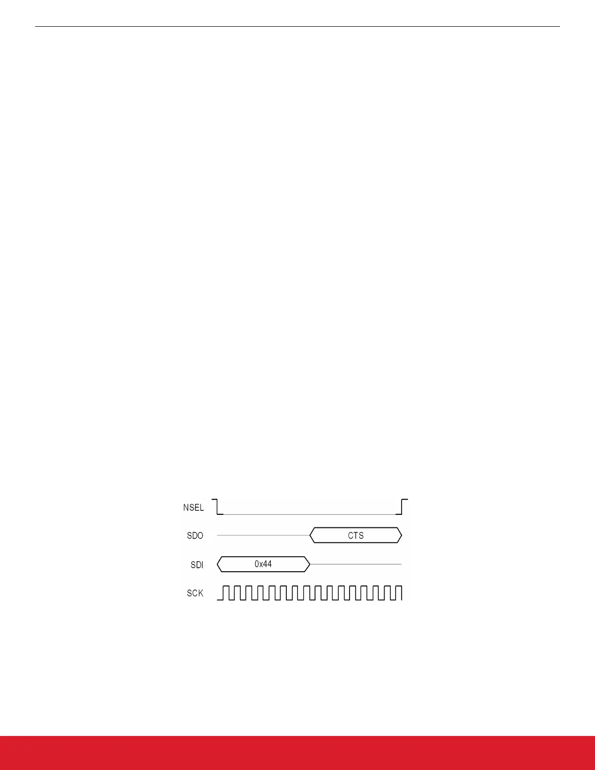
To ensure the radio is ready to receive the next command, the host MCU has to pull down the select (NSEL) pin to monitor the status of
clear to send (CTS) over the SPI port. The 0x44 command ID has to be sent and eight clock pulses have to be generated on the SCLK
pin. During the additional eight clock cycles, the radio clocks out the CTS as a byte on the SDO pin. When completed, NSEL should be
pulled back to high. If the CTS byte is 0xFF, it means that the radio processed the last command successfully and is ready to receive
the next command; in any other case, the CTS read procedure has to be repeated from the beginning as long as the CTS byte is not
0xFF.
Figure 4.1. Software Polling
4.3.2 GPIO Checking Method
Any GPIO can be configured for monitoring CTS. GPIOs can be configured to go either high or low when the chip has completed the
command. The function of the GPIOs can be changed by the GPIO_PIN_CFG command. By default, GPIO1 is set as "High when com-
mand completed, low otherwise" after power-on reset. Therefore, this pin can be used for monitoring CTS right after power-on reset to
know when the chip is ready to boot up.
AN954: Programming Guide for EFM8 and EZRadio ®
Application Programming Interface
silabs.com | Smart. Connected. Energy-friendly. Rev. 0.1 | 17