1
3
5
7
9
11
13
15
17
19
GND
NC
NC
NC
NC
NC
NC
SCL
3V3
GND
GND
NC
NC
NC
NC
NC
NC
SDA
3V3
GND
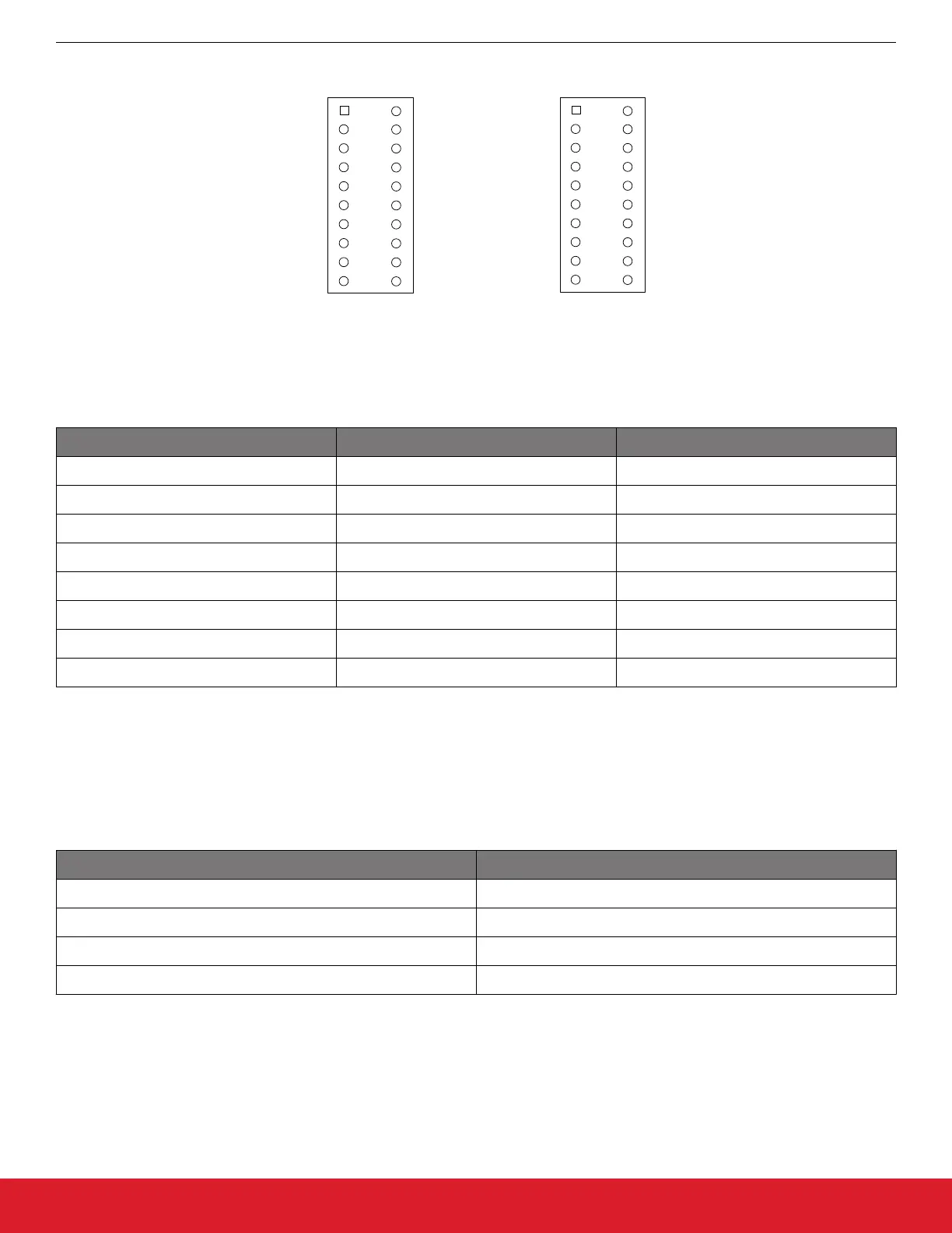
RFP2 Connector
2
4
6
8
10
12
14
16
18
20
1
3
5
7
9
11
13
15
17
19
GND
MOSI
SCLK
RF_NIRQ
SDA
RF_GPIO_0
RF_GPIO_2
NC
VRF
GND
GND
MISO
RF_NSEL
RF_SDN
SCL
RF_GPIO_1
RF_GPIO_3
NC
VRF
GND
RFP1 Connector
2
4
6
8
10
12
14
16
18
20
Figure 1.5. RFP1 and RPF2 Connectors
Table 1.1. EZRadio to EFM8 Connections
Pin Name Pin Function BB1 STK Pin
GND Ground GND
VDD Voltage Supply VDD
NIRQ Interrupt output, active low P0.0
SDN Shutdown input, active high P1.5
NSEL SPI select input P1.1
SCLK SPI clock P1.0
SDI SPI data input P0.6
SDO SPI data output P0.7
1.5 Radio Hardware Interface
The EZRadio devices can be controlled by the host MCU over a SPI bus and six additional signals. The user has access to the radio's
API via the SPI bus.
Table 1.2. SPI Signals
Signal Description
SCLK Serial clock, output from master
SDI Master output, slave input(MOSI)
SDO Master input, slave output(MISO)
NSEL Slave select, active low
The high state of the shutdown (SDN) pin is used to completely disable the radio and put the device into the lowest power consumption
state. The radio has an interrupt output pin (NIRQ) that can be used to promptly notify the host MCU of multiple events. The NIRQ pin is
active low and goes back to high if the pending interrupt flag is cleared by reading the appropriate interrupt pending registers.
AN954: Programming Guide for EFM8 and EZRadio ®
Hardware
silabs.com | Smart. Connected. Energy-friendly. Rev. 0.1 | 4