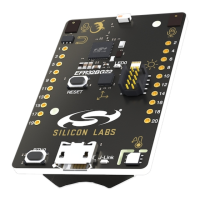
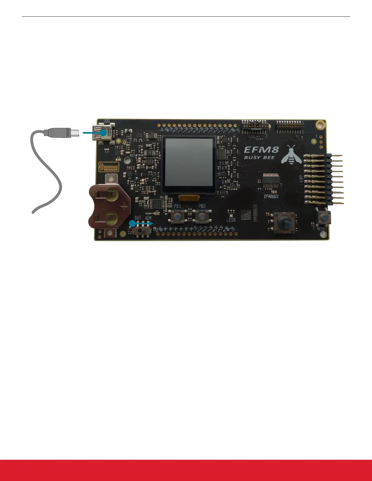
1.6 Setting Up the Hardware
1. Connect an RF Pico Board to the expansion board via the RFP1/2 connectors.
2. Connect the antenna to the SMA connector on the RF Pico Board.
3. Connect the BB1 starter kit to the expansion board via the 20 pin header.
4. Provide power to the board by connecting the DBG USB connector to the PC using the provided USB cable.
5. Move the switch to the AEM position.
6. Wait for Windows to install the driver of the debug interface, if necessary.
Figure 1.6. Setting up the BB1 STK
AN954: Programming Guide for EFM8 and EZRadio ®
Hardware
silabs.com | Smart. Connected. Energy-friendly. Rev. 0.1 | 5