10 INSTALLATION OF PRODUCT
10.1 Installation Scheme and Parts
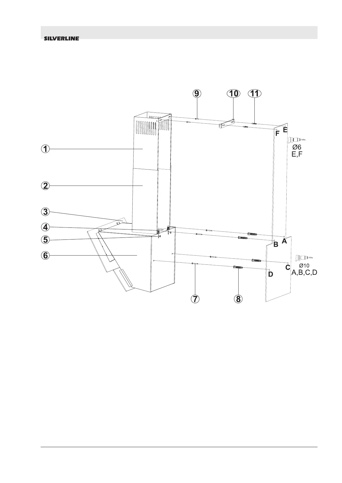
Fig. 11: ASSEMBLY INSTALLATION AND COMPONENTS
1- Inner Flue
2- Outer Flue
3- Glass
4- Hanging Plate of Cooker Hood
5- Hanging Plate of Cooker Hood Fixing Screw
5- 2x 3.9x22 Flue Connection Plate Screw
6- Body
7- 4x Ø10mm Plastic Dowel
8- 4x 5.5x60 Wall Mount Screw
9- 2x 3.9x22 Screw
10- Flue Connection Plate
11- 2x Ø6mm Plastic Dowel
n Loosening the product hanging plate fixing screw (5) pull the
hanging plates (4) upwards, and fix the hanging plated by re-
tightening the fixing screw (Fig. 11).
n Assemble the cooker hood with the help of the assembly
scheme (Fig. 11).
n Affix the assembly pattern on the wall, at the specified height
(See the minimum and maximum distances intended for the
worktop, in the assembly pattern). Perforate points A, B, C and
D (Fig. 11)
INSTALLATION OF PRODUCT
Installation Scheme and Parts
28.12.2017 HOOD USER GUIDE ENGLISH 19