SYSTEM OPERATIONS-15
DC ELECTRICAL SYSTEM
DC ELECTRICAL SYSTEM COMPONENTS
Batteries
Battery Switches
Fuse Box - Salon
Fuse Box - Bridge
Panel - Main - Salon
Helm Accessory Switches
Battery Charges
BATTERIES:
The DC Electrical System obtains its power from the
batteries. The batteries are located in the Engine
Room. There are the Generator Batteries, the Star-
board Batteries, and the Port Batteries. The quantity
of each group depends on the engine option. All
batteries are 12 volt.
NEGATIVE GROUND SYSTEM
The negative terminal of each battery is attached to
a grounding stud on each engine. This is known as
a Negative Ground System and is the approved
system for marine DC electrical systems. The bat-
tery wiring system has two color-coded wires. The
yellow wire is the ground (negative) wire and the red
wire is the positive (hot) wire.
BATTERY SWITCHES:
The batteries are directly connected to the Battery
Switches. The battery switch has two positions -
ON and OFF. When the battery switches are in the
OFF position, the entire DC Electrical System is OFF
(except for the memory).
Generator Battery Switch:
The Generator Battery Switch is located forward
of the Generator in the Engine Room. This switch
determines if the battery power is ON or OFF to the
generator. The Generator supplies AC Power, not
DC Power.
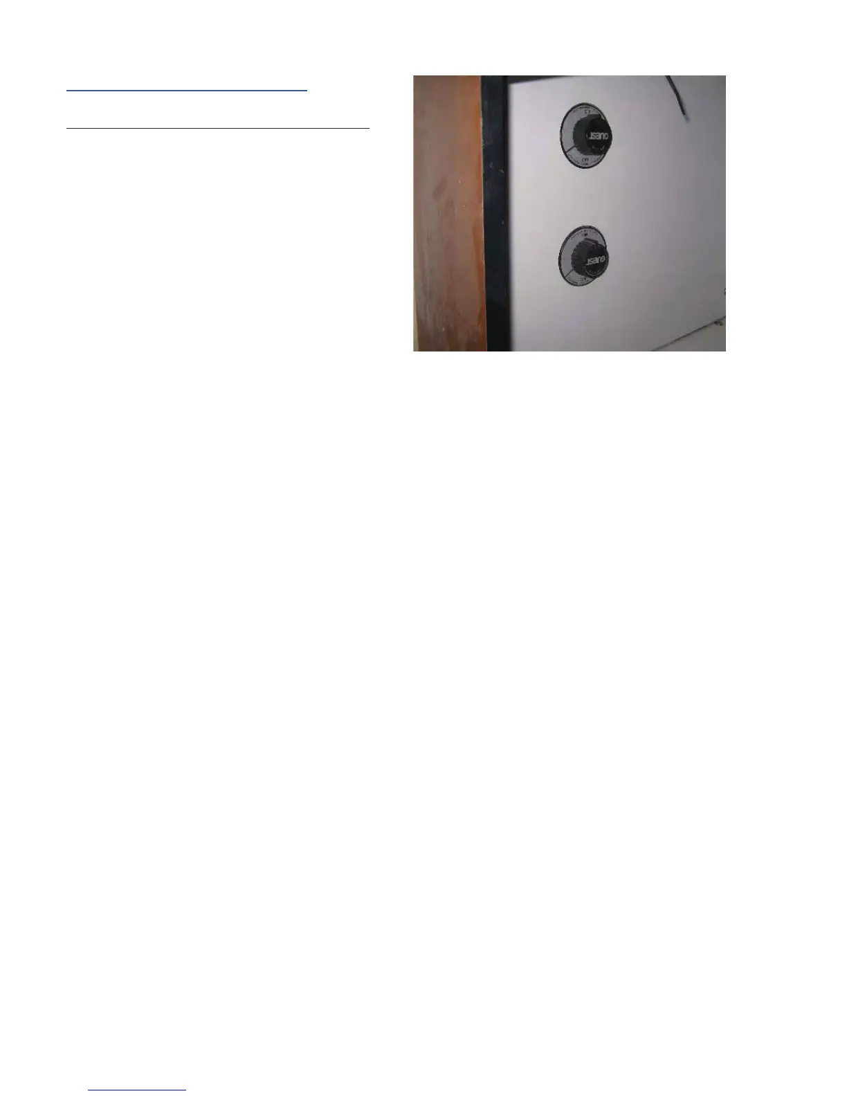
Starboard and Port Battery Switches:
The Starboard and Port Battery Switches are lo-
cated inside the Salon, to the lower port side of the
entry door. The photo above shows the battery
switches.
•
•
•
•
•
•
•
These switches control the entire DC System. If the
switches are OFF, no DC Power at all is activated
on your boat.
NOTE: The Bilge Pumps, Carbon Monoxide Moni-
tors, and Radio Memory are NOT disconnected
from their power source when the battery switch is
turned to the OFF position. These accessories are
connected directly to the battery and do not require a
switch for operation. There is also a breaker between
the battery and the memory section of the fuse box.
This breaker is located between the battery switches.
You would need to turn this breaker OFF to service
only these items.
The power from the Starboard Switch goes to:
Main Battery 2 Breaker on the DC Panel.
Bridge Electric Breaker on the DC Panel.
Parallel Start Switch at the Helm.
The power from the Port Switch goes to:
Main Battery 1 Breaker on the DC Panel.
Helm Accessory Breaker on the DC Panel.
Parallel Start Switch at the Helm.
•
•
•
•
•
•