Smart Machine Smart Decision
SIM7600E_SIM7600E-H-PCIE_Hardware_Design_V1.00 30 2017-11-23
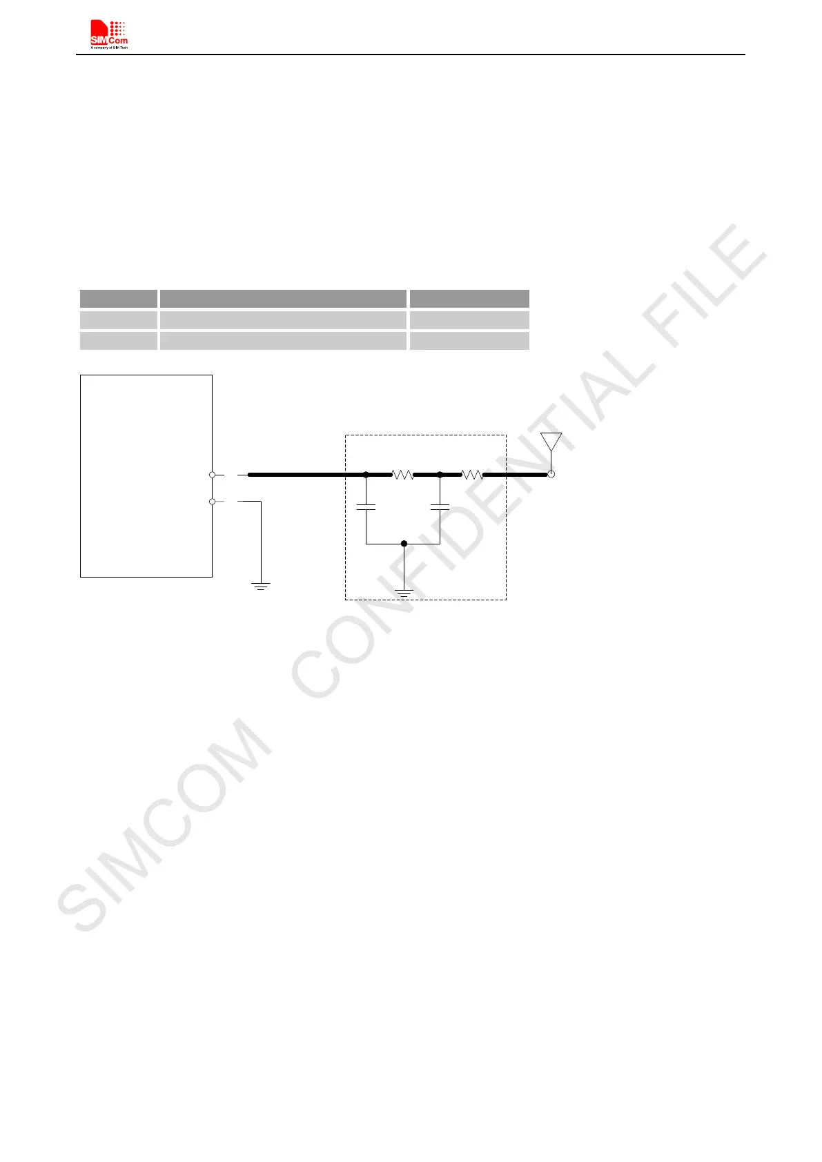
In above figure, the components R1,C1,C2 and R2 are used for antenna matching, the value of components can
only be got after the antenna tuning, usually, they are provided by antenna vendor. By default, the R1, R2 are 0Ω
resistors, and the C1, C2 are reserved for tuning.
The RF test connector in the figure is used for the conducted RF performance test, and should be placed as close
as to the module’s antenna pin. The traces impedance between components must be controlled in 50Ω.
The
component D1 is a Bidirectional ESD Protection device, which is suggested to add to protection circuit, the
recommended Part Numbers of the TVS are listed in the following table:
Table 22: TVS part number list
R4
C3
MODULE
59
AUX_ANT
GND
C4
58
R3
Matching circuit
AUX ANT
Figure 22: Antenna matching circuit (AUX_ANT)
In above figure, R3, C3, C4 and R4 are used for auxiliary antenna matching. By default, the R3, R4 are 0Ω
resistors, and the C3, C4 are reserved for tuning.
Note
:
SIMCom suggests the LTE auxiliary antenna to be kept on, since there are many high bands in the
designing of LTE-TDD, such as band38, band40 and band41.
5.3 GNSS
SIM7600E-PCIE merges GNSS (GPS/GLONASS/BD) satellite and network information to provide a
high-availability solution that offers industry-leading accuracy and performance. This solution performs well,
even in very challenging environmental conditions where conventional GNSS receivers fail, and provides a
platform to enable wireless operators to address both location-based services and emergency mandates.
5.3.1 GNSS Technical specification
Tracking sensitivity: -159 dBm(GPS)/-158 dBm(GLONASS)/-159dbm (BD)
Cold-start sensitivity: -148 dBm
Accuracy (Open Sky): 2.5m (CEP50)
TTFF (Open Sky) : Hot start <1s, Cold start<35s
Receiver Type: 16-channel, C/A Code
GPS L1 Frequency: 1575.42±1.023MHz