32
6.12.5 Separate ducts (Ø 60mm and Ø 80mm)
Constructing outlets for separate ducts indicates the use of
the "air-smoke split pipe system". This is to be ordered sep-
arately from the boiler and when connected to the other ac-
cessories, from those listed in the table below, completes the
smoke-outlet/ combustion air inlet assembly.
Separate accessories
Description
Code
Diame-
ter Ø 60
(mm)
Diame-
ter Ø 80
(mm)
Air-smoke split pipe system (without take-
off point)
8093060 -
Air-smoke split pipe system (with take-off
point)
- 8093050
90° curve M-F (6 pieces) 8089921 8077450
90° curve M-F (with take-off point) 8089924 -
M-F 80/60 reduction 8089923 -
M-F 80/50 reducer - 8089941
Extension W. 1000 mm (6 pieces) 8089920 8077351
Extension W. 500 mm (6 pieces) - 8077350
Extension W. 135 mm (with take-off point) - 8077304
Wall outlet terminal 8089541 8089501
Internal and external ring nut kit 8091510 8091500
Inlet terminal 8089540 8089500
45° curve M-F (6 pieces) 8089922 8077451
Manifold 8091400
Tile with joint 8091300
Roof outlet terminal W. 1390 mm 8091204
Inlet/outlet fitting Ø 80/125 mm - 8091210
Duct kit C(10)3 model
Edea T
25
- 6296550
Duct kit C(10)3 models
Edea T
35
- 6296543
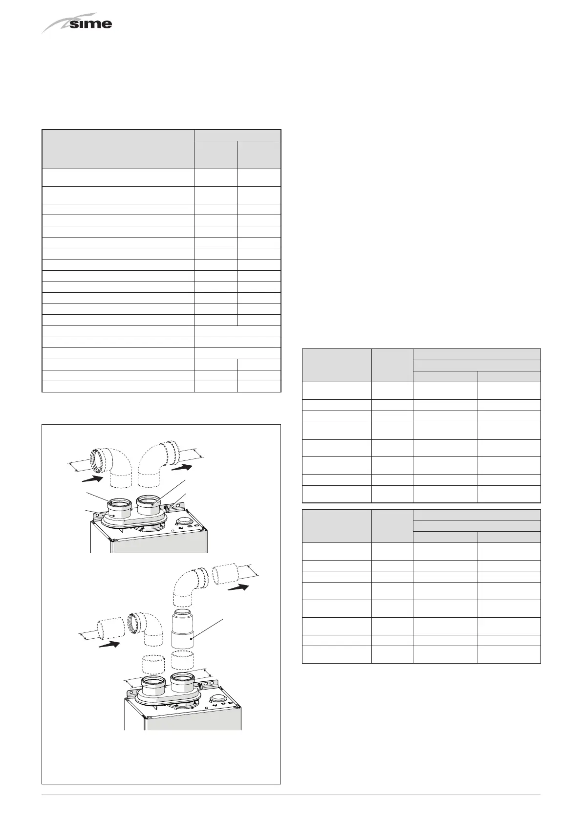
Twin flue adaptor
1
2
3
4
5
Ø80
Ø80
Ø50
Ø80
1
Twin flue adaptor with
flue gas analysis points
2
Air inlet
3
Exhaust outlet
4
Take-off point for smoke
analysis
5
Ø80/50 reducer
Fig. 28
NOTE:
the ducts can be reduced from Ø80 to Ø50 by using
the reducer with code 8089941, to be ordered separately, as
shown in "Fig. 17".
m
CAUTION
–
The maximum total length of the ducts
, obtained by
adding the lengths of the inlet and outlet pipes, is
determined by the load losses of the individual ac-
cessories used and
must not exceed 16.5 mm H2O
for
Edea 25 T
and
30.0 mm H2O
for
Edea 35 T
.
–
For all boiler versions, the total extension
must not
in any case exceed 25 m (inlet) + 25 m (outlet) for
ducts Ø 80 mm. For Ø 60 mm ducts, the total ex-
tension must not exceed, respectively, 18 m (suc-
tion) + 18 m (discharge) for model
Edea 25 T
and 16
m (suction) + 16 m (discharge) for model
Edea 35
T
, even if the total load loss is below the maximum
applicable level.
m
CAUTION
For model
Edea 25 T
, beyond a total load loss between
discharge and suction of
9 mm H2O
, remove the dis-
charge diaphragm as illustrated in “Fig. 27”.
For model
Edea 35 T
, beyond a total load loss between
discharge and suction of
12 mm H2O
, remove the dis-
charge diaphragm as illustrated in “Fig. 27”.
Load loss accessory Ø 60 mm
Description Code
Load loss (mm H
2O)
Edea 25 T
Inlet Outlet
Air/smoke split
pipe system
8093060 2,5 0,5
90° curve MF 8089921 0,4 0,9
45° curve MF 8089922 0,35 0,7
Horizontal exten-
sion W. 1000 mm
8089920 0,4 0,9
Vertical extension
W. 1000 mm
8089920 0,4 0,6
Wall outlet ter-
minal
8089541 _ 1,2
Wall inlet terminal 8089540 0,5 _
Roof outlet termi-
nal (*)
8091204 0,8 0,1
Description Code
Load loss (mm H
2O)
Edea 35 T
Inlet Outlet
Air/smoke split
pipe system
8093060 2,5 0,5
90° curve MF 8089921 0,6 1,4
45° curve MF 8089922 0,55 1,2
Horizontal exten-
sion W. 1000 mm
8089920 0,6 1,4
Vertical extension
W. 1000 mm
8089920 0,6 0,8
Wall outlet ter-
minal
8089541 _ 1,6
Wall inlet terminal 8089540 1,1 _
Roof outlet termi-
nal (*)
8091204 1,5 0,2