36
m
CAUTION
The adjustment of the Maximum Heating Tempera-
ture is managed by
"PAR 14"
(see paragraph "List of
parameters").
6.13.2 External timers and Room Thermostats
The heat demand can be by a "clean contact" conforming to
EN607301 connected to TA (see section
"Wiring diagram"
) or
by use of a dedicated Sime Remote Control (Home or Home
Plus). The boiler will automatically detect when a dedicated
control is connected.
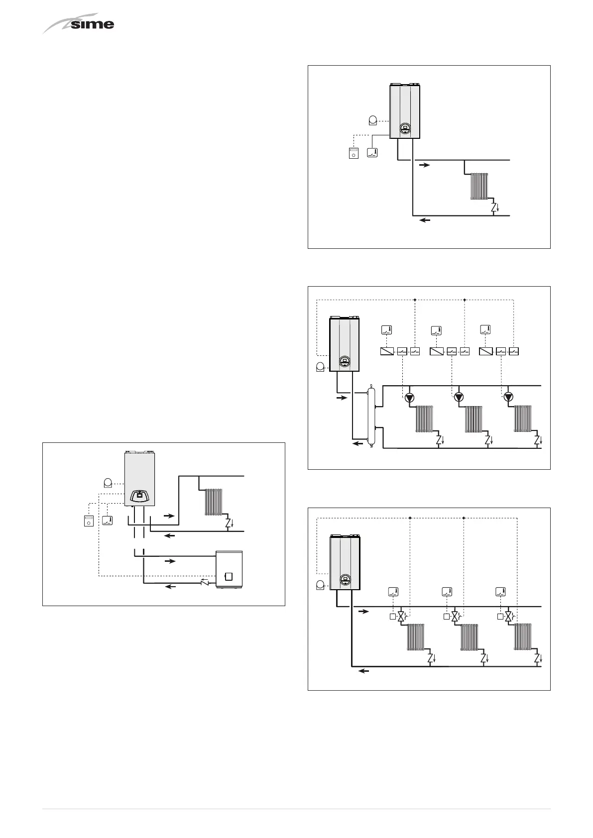
6.13.3 EXAMPLE of use of the command/control
device on some types of heating systems
KEY
M System flow
R System return
Mb Hot water tank delivery
Rb Hot water tank return
CR Remote control
EXP Expansion card
SE External temperature sensor
SBL Hot water tank sensor (SB)
TA Room thermostat for boiler activation
TZ1÷TZ3 Room thermostat for the zone
VZ1-VZ3 Zone valves
RL1-RL3 Zone relays
P1-P3 Zone pump
SP Hydraulic separator
IP Floor system
VM Thermostatic mixer valve
TSB Low temperature safety thermostat
ONE DIRECT ZONE system and REMOTE HOT WATER TANK,
external sensor and room thermostat or, alternatively, re-
mote control.
R
M
Mb Rb
SE
TA
SBL
Fig. 38
m
CAUTION
The boiler is pre-arranged for connection to a re-
mote hot water tank. To use the boiler for HEATING
ONLY:
– disconnect the hot water tank sensor (SBL)
– set "PAR 02 = HYDRAULIC CONFIGURATION" to 1.
This operation must only be carried out by Profes-
sionally Qualified Personnel during the boiler com-
missioning phase.
ONE DIRECT ZONE system, external sensor and room ther-
mostat.
R
M
SE
TA
Fig. 39
MULTI ZONE system - with pump, room thermostat and ex-
ternal sensor.
TA
TZ2
TZ3
TZ1
P3
RL1
SP
RL2 RL3
P2P1
R
M
Fig. 40
MULTI ZONE system - with zone valve, room thermostat and
external sensor.
TA
TZ1
VZ1 VZ2 VZ3
TZ2 TZ3
R
M
Fig. 41
m
CAUTION
Set the parameter "tS 17 = DELAY SYSTEM PUMP
ACTIVATION to allow the opening of zone valve Vz.