45
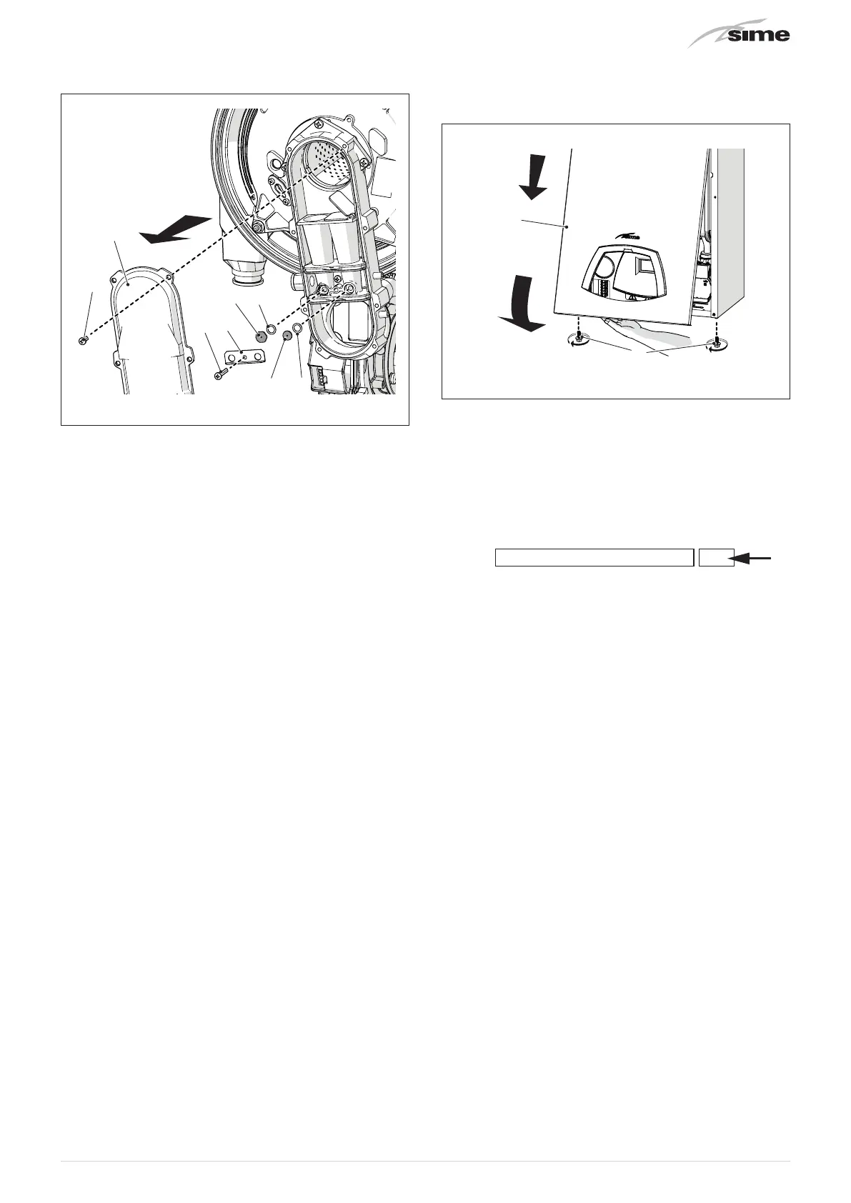
– loosen the eight screws (3) and remove the cover (4)
– unscrew the screw (5) and remove the plate (6)
7
5
6
8 9
9
3
4
Fig. 54
– replace the two distinct nozzles (7) and (8) and the related
O-ring (9) with those provided in the conversion kit. Having
two distinct nozzle heads avoids them being inverted during
assembly
– refit the plate (6) and cover (4) following the above instruc-
tions in reverse order
– replace the smoke outlet diaphragm, if present in the trans-
formation kit, as illustrated in "Fig. 27"
– access the installer parameters and modify parameter PAR
01 on the basis of the power and gas used, as indicated in
the table in the “Circuit Board Replacement”) paragraph
– perform the “Chimney sweep function” function to correct-
ly set the CO
2 of the boiler with the new gas and then mount
the front panel (2) back on, securing it with the two screws
(1).
2
Fig. 55
m
CAUTION
Conversion may ONLY be carried out by Profession-
ally Qualified Personnel.
m
CAUTION
If the gas supply is changed from G20 to G31, mark
the box on the TECHNICAL DATA PLATE.
G31 - 37 mbar