17
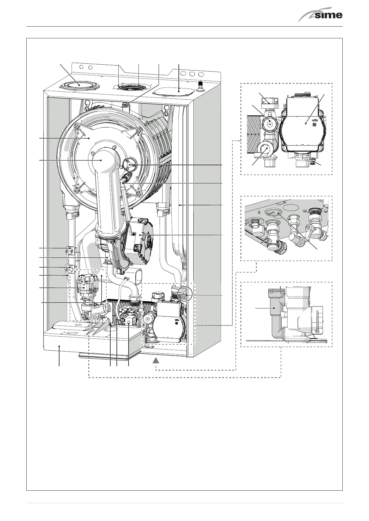
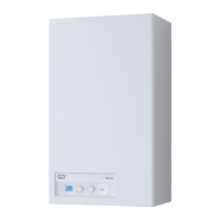
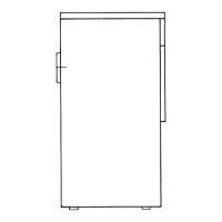
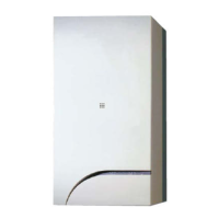
5.4 Structure
13
29
14
16
17
18
15
1
2
9
20
21
22
23
19
3
5
6
7
10
4
118 12
1
Combustion chamber door
2
Air/gas duct
3
Safety thermostat
4
Air-gas mixer
5
Boiler delivery sensor
(SMC)
6
Condensate siphon
7
Diverter valve
(VD)
8
Domestic hot water sensor
(SS)
9
Control panel
10
Venturi air exhaust pipe
11
DHW exchanger
(SP)
12
Gas valve
13
Pressure gauge
(MA)
14
Flow meter
(FLM)
15
System relief valve
(VS)
16
System drainage outlet
(SI)
17
System circulator pump
18
Water pressure transducer
(TPAC)
19
Automatic bleed valve
20
Fan
(V)
21
Expansion vessel
(VE)
22
Ignition/detection electrode
(EAR)
23
Flame viewing window
24
Air inlet closing plate (separate
ducts)
25
Exhaust sensor
(SF)
26
Smoke outlet duct
(CSFU)
27
Boiler air inlet duct (concentric
ducts)
(CAA)
28
Plug/socket for attaching the air in-
let pipe (separate ducts)
29
By-pass
Fig. 11