34
6.13.2 External timers and Room Thermostats
The heat demand can be by a "clean contact" conforming to
EN607301 connected to TA (see section
"Wiring diagram"
) or
by use of a dedicated Sime Remote Control (Home or Home
Plus). The boiler will automatically detect when a dedicated
control is connected.
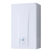
6.13.3 EXAMPLE of use of the command/control
device on some types of heating systems
KEY
SE External temperature sensor
TA Room thermostat for boiler activation
TZ1÷TZ3 Room thermostat for the zone
EVZ1-EVZ3
Zone solenoid valve
KA1-KA3
Zone relays
PI1-PI3 Zone pump
SP Hydraulic separator
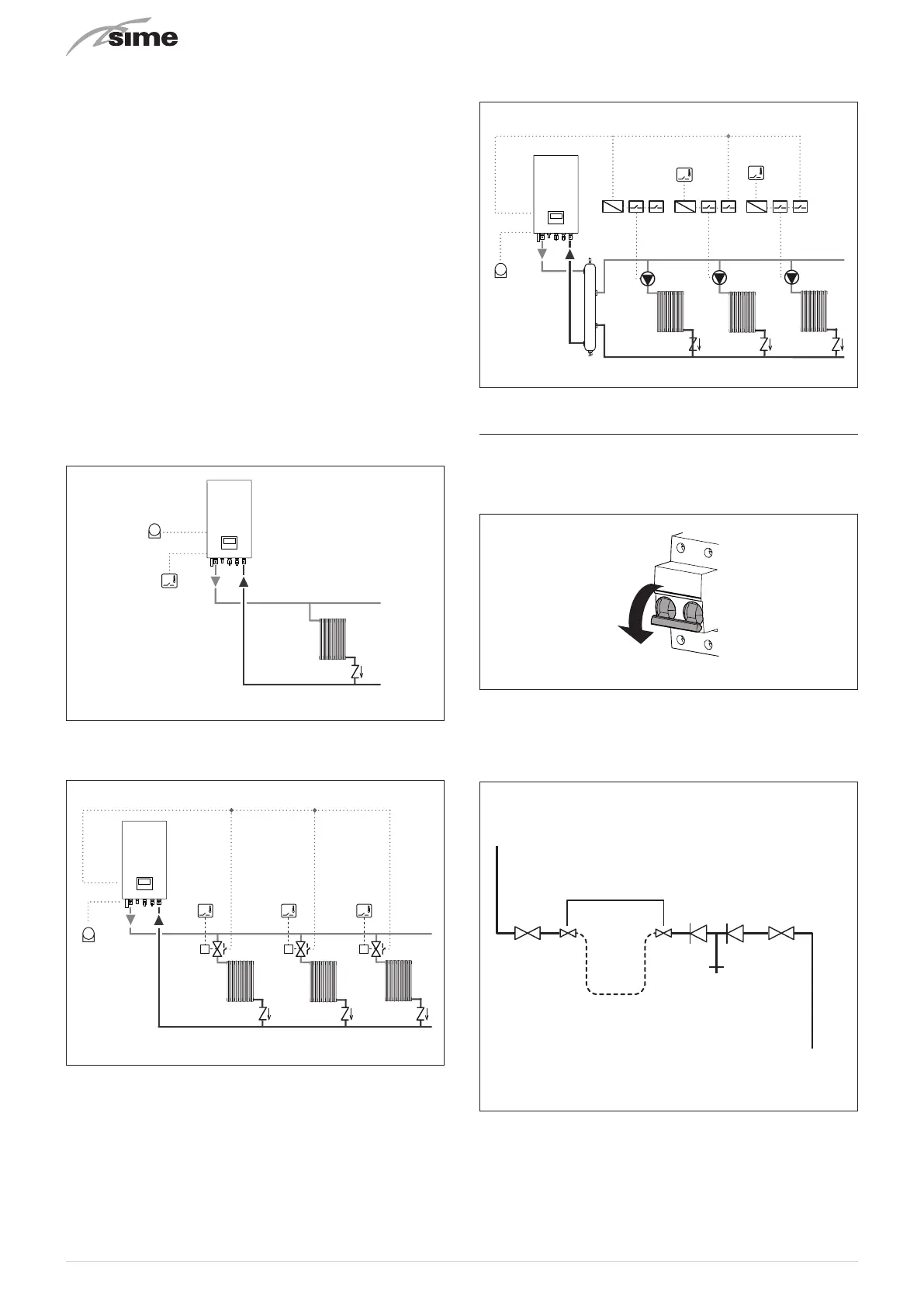
ONE DIRECT ZONE system, external sensor and room ther-
mostat.
SE
TA
SE
TA1
Fig. 33
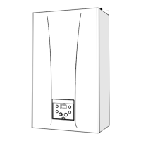
MULTI ZONE system - with zone valve, room thermostat and
external sensor.
TZ1
EVZ1 EVZ2 EVZ3
TZ2 TZ3
SE
TA1
SE
Fig. 34
m
CAUTION
Set the parameter "tS 1.7 = DELAY SYSTEM PUMP
ACTIVATION to allow the opening of zone valve VZ.
MULTI ZONE system - with pump, room thermostat and ex-
ternal sensor.
SE
TZ2
TZ3
PI3
KA1
SP
KA2 KA3
PI2PI1
TA1-TA2
SE
Fig. 35
6.14 Refilling or emptying
Before carrying out the operation described below, isolate the
boiler power supply.
Ensure that the inhibiter concentration is correct on refilling.
Fig. 36
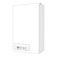
6.14.1 Method of filling a sealed system
A sealed system must only be filled by a competent person
using a method similar to that shown in figure below.
Stop
valve
Stop
valve
TAP
Hose
unions
Double check
valve
Filling loop
temporarily connected
Mains
water supply
Heating
cicuit return
Fig. 37