19
DESCRIPTION
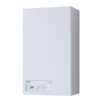
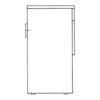
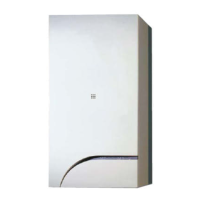
GIULIA COMBI
30
COMBUSTION DATA
Smoke temperature at Max/Min flow (80-60°C) °C 82 / 67
Smoke temperature at Max/Min flow (50-30°C) °C 68 / 50
Smoke flow Max/Min g/s 14,2 / 2,3
CO
2 at Max/Min flow rate (G20) % 9,3 / 9,0
CO
2 at Max/Min flow rate (G31) % 10,2 / 10,0
NOx measured (*) mg/kWh 32
NOZZLES GAS
Number of nozzles No. 1
Nozzle diameter (G20-G31) mm 5,3 / 4,2
Gas consumption at Max/Min flow rate (G20) m
3
/h 3,17 / 0,51
Gas consumption at Max/Min flow rate (G31) kg/h 2,33 / 0,37
Gas supply pressure (G20/G31)
mbar 20 / 37
kPa 2 / 3,7
TEMPERATURE PRESSURE
Max operating temperature °C 85
Heating adjustment range °C 20÷80
Domestic hot water adjustment range °C 10÷60
Max operating pressure
bar 3
kPa 300
Water content in boiler l 2,55
(*) Calculated with upper calorific value (Hs)
Lower Heat Output (Hi)
G20 Hi.
9.45 kW/m
3
(15°C, 1013 mbar) -
G31 Hi.
12.87 kW/kg (15°C, 1013 mbar)
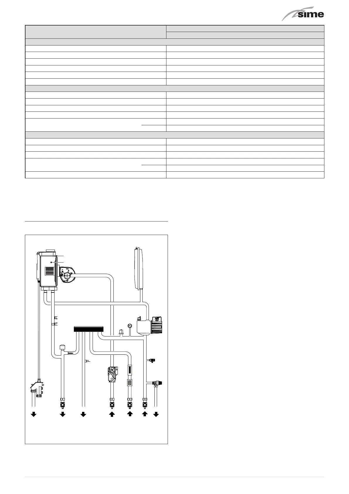
5.6 Main water circuit
3
4
5
14
13
15
16
18
19
109
7
11
17
20
12
6
8
2
1
21 22 23 24
Fig. 12
KEY:
M System flow
R System return
U Domestic hot water outlet
E Domesti hot water inlet
S Safety valve outlet
G Gas supply
Sc Condensate outlet
1
Condensing heat exchanger
2
Combustion chamber
3
Fan
4
Thermal safety thermostat
5
Delivery sensor
6
Domestic hot water heat exchanger
7
Water pressure transducer
8
Pressure gauge
9
Automatic bleed valve
10
Pump
11
System expansion vessel
12
Diverter valve
13
Automatic by-pass
14
Domestic hot water sensor
15
Gas valve
16
Domestic hot water flow meter
17
Domestic hot water filter
18
Boiler drain
19
System relief valve
20
Condensate siphon outlet
21
System flow cock
22
Gas cock
23
Domestic hot water inlet cock
24
System return cock