The 4006 supports up to four annunciator options
including:
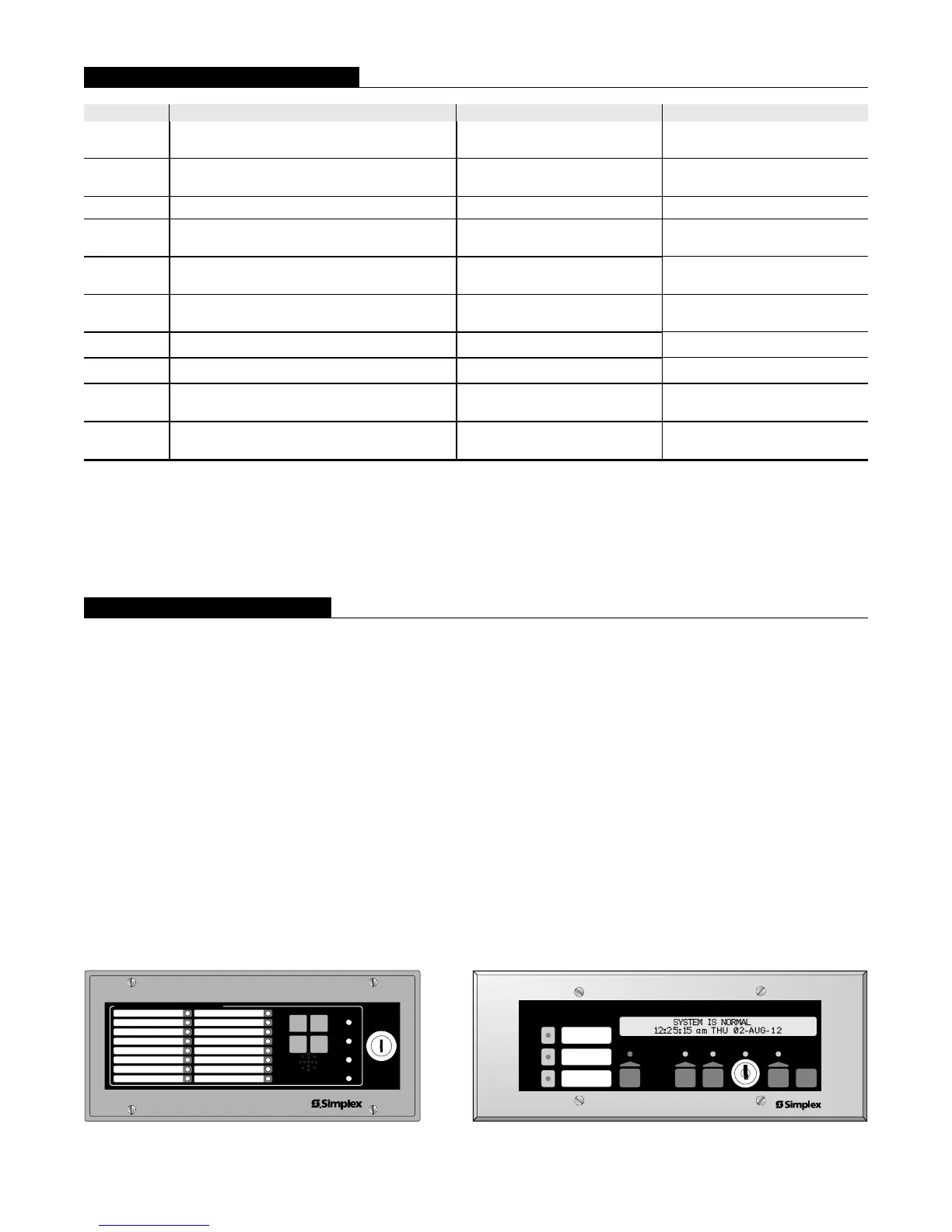
Door Mounted 24 LED Annunciator
4610-9111 Remote LED/Switch Annunciators
4606-9101 Remote LCD Annunciators
Annunciators communicate at a rate of 9600 baud with
24 VDC power supplied by separate wiring.
4610-9111 LED Annunciator Features:
16 LEDs with programmable functions and dedicated
LEDs for Alarm Silenced, Lost Communications,
Trouble, and Power-on
Keyswitch access controlled switches for
Acknowledge, Alarm Silence, Reset, and Lamp Test
Local tone-alert
4610-9111 LED/Switch Annunciator
4606-9101 LCD Annunciator Features:
LCD readout with two lines of 40 characters each and
LED backlighting
Wide viewing angle, super-twist design
Keyswitch access controlled
Control switches and status LEDs for:
Alarm, supervisory, or trouble acknowledge
Alarm silence and System Reset
Three programmable LED indicators:
Two LEDs are selectable as red or yellow
One LED is selectable as green or yellow
With provisions for custom labeling
4606-9101 LCD Annunciator
5 S4006-0001-8 8/2012
Model Module Supervisory Alarm
4006-9101
4006-9102
Standard fire alarm control panel 130 mA
160 mA
+ 60 mA per IDC in Alarm
4006-9121
4006-9122
Control panel with 24 LED Annunciator 148 mA
210 mA
+ 60 mA per IDC in Alarm
4006-9801 Expansion Power Supply 50 mA 60 mA
4006-9802 Expansion IDC Module 50 mA
50 mA
+ 60 mA per IDC in Alarm
4006-9803 Expansion Relay Module
0 mA
+ 10 mA per energized relay
0 mA
+ 10 mA per energized relay
4006-9804 Five Circuit IDC Class A Adapter
0 mA normal;
10 mA per IDC in trouble
0 mA normal;
10 mA per IDC in trouble
4006-9805
City Circuit Module with disconnect switch
30 mA 60 mA
4006-9806
City Circuit Module without disconnect switch
30 mA 60 mA
4606-9101
Remote LCD Annunciator (see data sheet
S4606-0001)
65 mA 140 mA
4610-9111
Remote LED/Switch Annunciator (see data
sheet S4610-0001)
40 mA
70 mA
(all LEDs and tone-alert on)
** Current Calculation Information:
1. To determine total supervisory current, add currents of modules in panel to base system value and all auxiliary loads.
2. To determine total alarm current, add currents of modules in panel to base system alarm current and add all panel NAC loads
and all auxiliary loads.
Fire Alarm Annunciator
ACK
RESET
ALARM
SILENCE
LAMP
TEST
ALARM
SILENCED
LOST COM
TROUBLE
POWER
CONTROL
ENABLE
FIRE
ALARM
ALARM
SILENCED
SYSTEM
SUPERVISORY
SYSTEM
TROUBLE
POWER
ON
SYSTEM
RESET
ALARM
ACK
SUPV
ACK
TBL
ACK
ALARM
SILENCE
Supervisory and Alarm Currents
Remote Annunciator Options