7
2098-9808
ALARM INDICATOR
OPTIONAL
(SEE ACCESSORIES)
OPTIONAL
(SEE ACCESSORIES)
RED
ALARM
LED
SEE
NOTES
2, 3
UL-LISTED
CONTROL PANEL
SIMPLEX 2120, 4010
4020, 4100+ OR 4120
MAPNET II / IDNet
+
-
SHIELD
(OPTIONAL)
SEE NOTE 1
SHIELD
SHIELD
TO OTHER
MAPNET II/
IDNet DEVICES
SEE NOTE 4
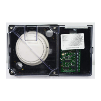
4098-9755
2-WIRE DUCT SENSOR
ADDRESS
SWITCH
ADDRESS
SWITCH
RED
BLK
1
ON
2
3
4
5
6
7
8
1
LED
TB1
SW2
2 3 4 5 6 7 8
+-
TEST MAP + MAP -
2098-9806
REMOTE ALARM
INDICATOR /
KEYSWITCH
RED
ALARM
LED
TEST
SEE NOTES 2,3
4098-9755
2-WIRE DUCT SENSOR
RED
BLK
1
ON
2
3
4
5
6
7
8
1
LED
TB1
SW2
2 3 4 5 6 7 8
+-
TEST MAP + MAP -
-
+
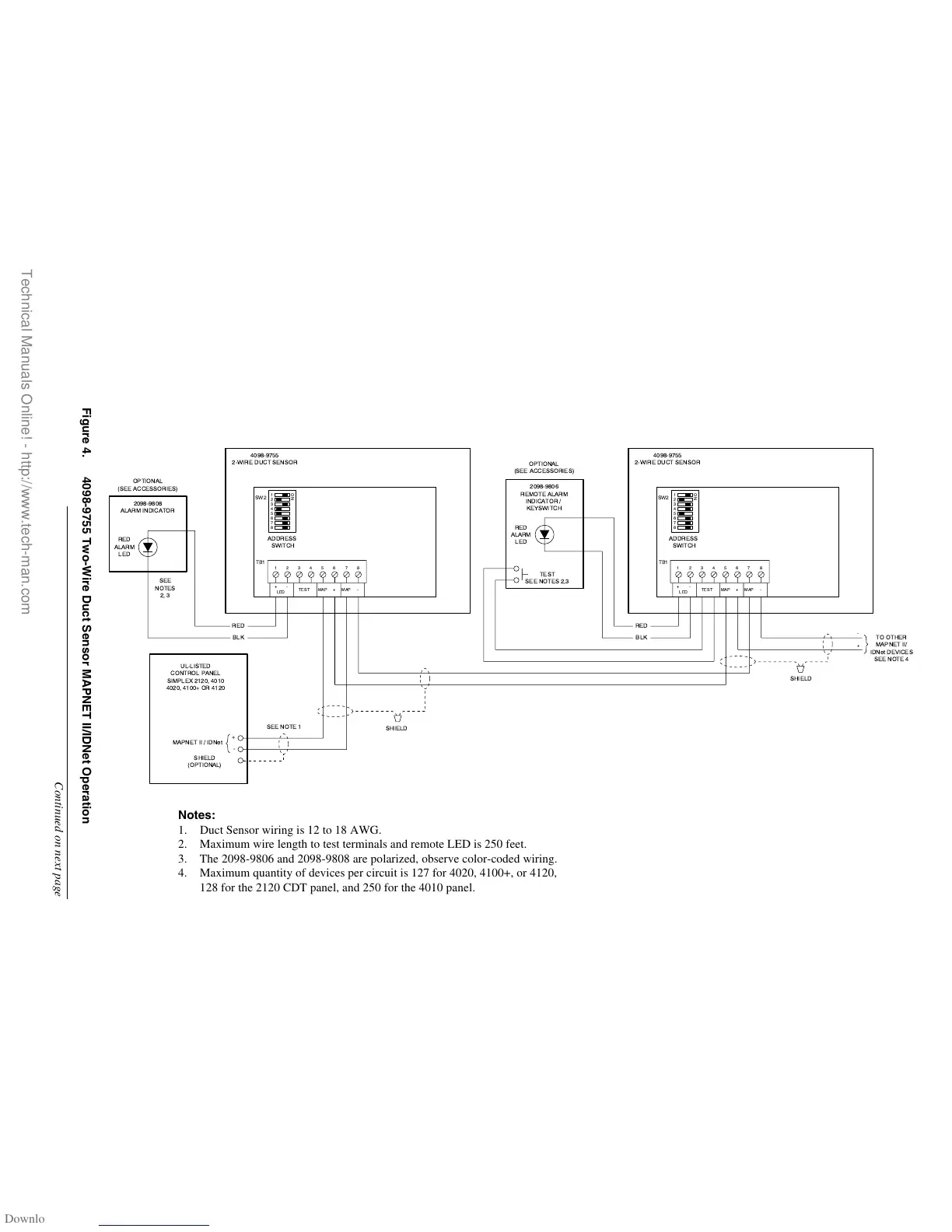
Figure 4. 4098-9755 Two-Wire Duct Sensor MAPNET II/IDNet Operation
Continued on next page
Notes:
1. Duct Sensor wiring is 12 to 18 AWG.
2. Maximum wire length to test terminals and remote LED is 250 feet.
3. The 2098-9806 and 2098-9808 are polarized, observe color-coded wiring.
4. Maximum quantity of devices per circuit is 127 for 4020, 4100+, or 4120,
128 for the 2120 CDT panel, and 250 for the 4010 panel.
Technical Manuals Online! - http://www.tech-man.com