9
An audio network contains one node with an audio controller module
(4100-1210 Analog Controller Board or 4100-1211 [or -1311] Digital Controller Board), and local
analog or digital amplifiers. Some configurations may have an audio controller module located in
a transponder end node; for example, an application with backup local audio in a non-head end
node or an application with distributed microphones.
Typically, the other nodes only contain amplifiers, the audio riser interface (a 4100-0621 Analog
Audio Riser, a 4100-0622 Digital Audio Riser or a 4100-1341 MCC Digital Audio Riser), and the
4100-0623 Network Audio Riser Controller Module.
The 4100-0623 Network Audio Riser Controller Module supports audio interconnections when
connected to 4100-0621 Analog Audio Risers, 4100-0622 Digital Audio Risers or 4100-1341
MCC Digital Audio Risers. It is a version of the Basic TIC that doesn’t have RUI input. It
communicates via internal communications and is used to control audio riser interface modules in
network nodes that are stand-alone fire alarm control panels.
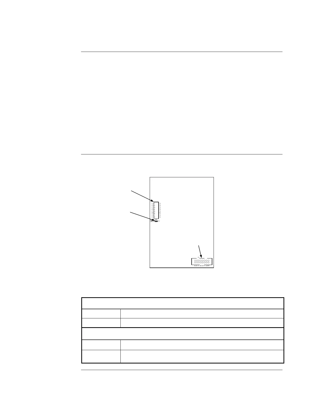
Figure 2 shows DIP switch, LED, and connector locations on the 4100-0623 Network Audio Riser
Controller Module.
Figure 2. Network Audio Riser Controller Module
Table 6. Network Audio Riser Controller Specifications
Electrical Specifications (4100-0623)
Input voltage 18-33 VDC
Input current 35 mA maximum
Electrical Specifications (4100-0621)
Input voltage 18-33 VDC
Input current 15 mA maximum
Network Audio Riser Controller Module
Audio Network
Configuration
Locations on the
Network Audio Riser
Controller Module
Network Audio Riser
Controller Module
Specifications
SW1. Baud
rate/device address
DIP switch
LED1. Illuminates
to indicate
communication loss
with the CPU
P3. Audio riser
module connector