7 S4100-0035-2 5/02
Slot 1 Slot 8Slot 7Slot 6Slot 5Slot 4Slot 3Slot 2
Expansion Bay Chassis
Block A
Block B
Block C
Block D
Block E
Block F
Block G
Block H
Size Definitions: Block = 4” W x 5” H card area
Slot = 2” W x 8” H motherboard with daughter card
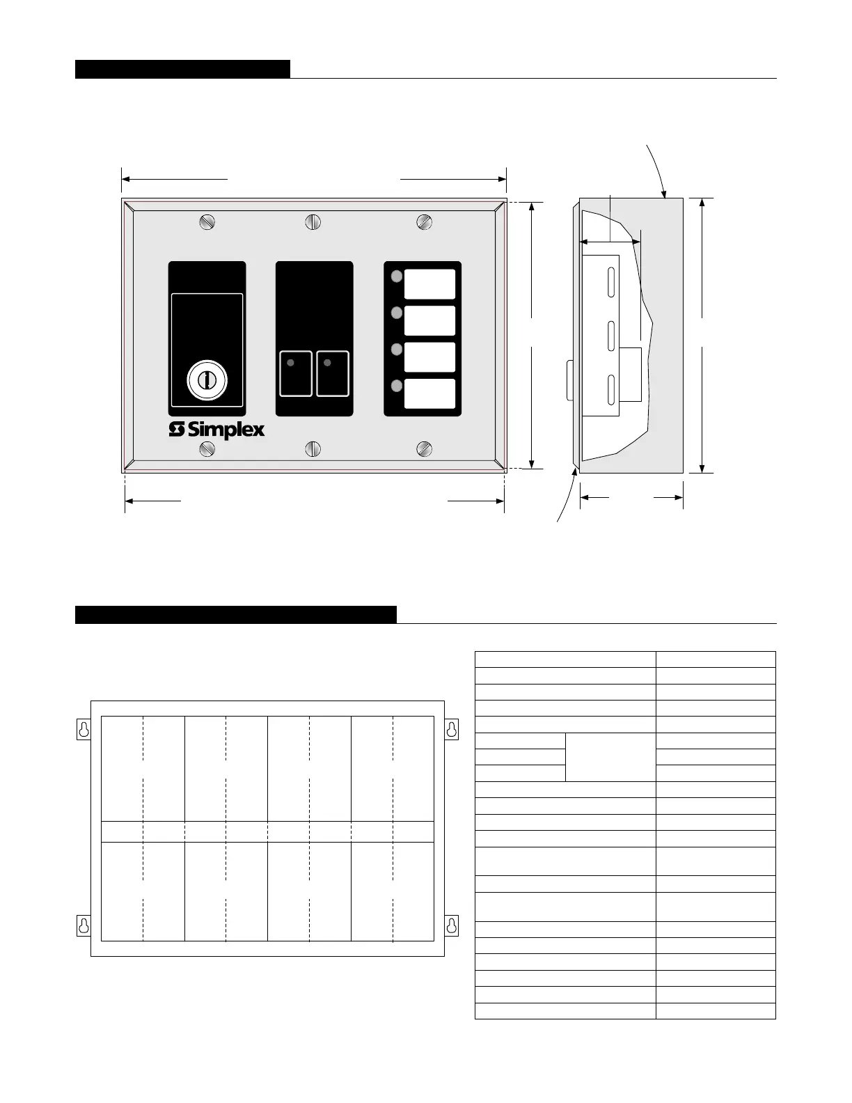
4-1/2"
(114 mm)
Local Mode Controller dimensions, 6-3/8" (162 mm)
Box dimensions, 6-1/2" (165 mm)
4-5/8"
(117 mm)
1-3/4"
(44 mm)
Matching box is supplied with surface mount
models 4601-9109 (red) and 4601-9111 (beige)
Fire Alarm Local Mode Controller
ENABLE
CONTROL
Alarm
Alarm
Silenced
Local
Mode
Active
Power
On
Alarm
Silence
Reset
Local
Mode
Control
See Operating Instruction 579-343
1" (25.4 mm)
into box
For semi-flush mounting, use a
1-1/2" deep (38 mm) 3-gang box
Expansion Bay Module Loading Reference
Description Mounting
Transponder Interface Modules Block A
Audio Riser Modules Block B
Terminal Block Module 1 Block
IDNet Modules 4” x 5”, 1 Block
4, 2 A Relays 2”, 1 Slot
4, 10 A Relays 4”, 2 Slots
8, 3 A Relays
NON
Power-limited
2”, 1 Slot
VESDA Interface 2”, 1 Slot
Class B IDC 2”, 1 Slot
Class A IDC 2”, 1 Slot
MAPNET II Module 4”, 2 Slots
MAPNET II Isolator
2”, 1 Slot, next to
MAPNET II Module
Decoder Module 6”, 3 Slots
System, Remote, or TrueAlert
Power Supply
Blocks E, F, G, H
ONLY
Expansion Power Supply Blocks G, H ONLY
NAC Expansion Module On XPS ONLY
Flex-50 Amplifiers Blocks E, F or C, D
100 W Amplifiers Blocks E, F, G, & H
100 W Backup Amplifiers Blocks A, B, C, & D
Telephone Expansion Module 1 Block
Local Mode Controller Detail