Page
11
3.0 DESCRIPTION AND SPECIFICATION
3.1 Introducon
This secon will provide a brief synopsis of the use of the load bank. Simplex, Inc.
reserves the right to change this synopsis, and this secon should only serve as a brief
concept of the device.
In this secon, you will nd:
— An overview of normal usage of the load bank.
— An overview of hardware capabilies.
— An overview of safety funcons.
3.2 Overview of Use
The Simplex Portable Load Bank is an ultra-compact, lightweight, and versale test
instrument specially designed for manufacturers, dealers, and users of AC power
systems. The load bank also provides roune maintenance exercise in order to assure
the long-term reliability and readiness of the standby generator. Exercise load banks
eliminate the detrimental eects of unloaded operaon of diesel engine generators. It
is suitable for tesng engine generators, wind generators, UPS systems, ground power
units, auxiliary power units, stac inverters, or virtually any other AC power source in
the producon line in the service shop or in the eld. The load of the unit can be applied
to all common AC voltages. See Table 1 under “3.5 Specicaons” on page 12 for a list
of specicaons for each type of load bank.
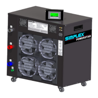
This fully self-contained load bank includes test instrumentaon, cooling system, rugged
load elements, load-applicaon control devices, and automac system protecon
devices. The resisve load elements in the load bank are cooled by a horizontal forced
air system. The load system is connected to the test source via the load cables.
3.3 Capabilies
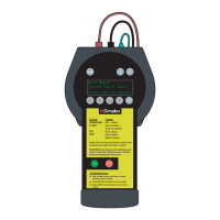
The load bank is a digitally controlled load bank with network capability. The unit is
controlled via a hand-held touchscreen controller that is connected to the load bank
by a supplied RS-232 network cable. It includes a digital power transducer with meter
displays on the touchscreen. Power load is applied via a screen keypad. Using the RS-232
cables, any number of load banks can be connected in a series. To create a load bank
chain, connect the RS-232 cables from the “out” connector to the “in” connector of the
next unit. Connue this process unl the desired number of units are connected. All
control and metering is provided from a single hand-held controller. All instrumentaon
values for the total network are summed and displayed on the master controller.
The load bank is highly portable and easily transported to the job site. The load bank
includes casters, liing, and moving handles. Power connecons plug in to Cam-Lok
connectors. Control and cooling fan power is obtained from a common 115v, 15A outlet
via the included connecon cord. The load bank is a fully self-contained and portable
tesng system. It includes integral cooling fans and control circuits, which can operate
from a supplied 120V control power cord.