| 9
Operation | HS70 User Manual
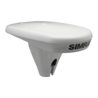
The heading arrow located on the bottom of the HS70 enclosure defines system orientation.
The arrow points in the direction the heading measurement is computed (when the antenna
is installed parallel to the fore-aft line of the vessel). The secondary antenna is directly above
the arrow.
¼ Note: The HS70 moving base station algorithm only uses GPS to calculate heading. Differen-
tial corrections are not used in this calculation and will not affect heading accuracy.
Supplemental Sensors
The HS70 has an integrated gyro and two tilt sensors. The gyro and tilt sensors are enabled
by default. Each supplemental sensor may be individually enabled or disabled. Both
supplemental sensors are mounted on the printed circuit board inside the HS70.
The sensors act to reduce the startup and reacquisition times. This improves the reliability and
accuracy of selecting the correct heading solution by eliminating other possible, erroneous
solutions. The table below provides a sensor operation summary.
Feature Normal Operation Coasting (no GPS)
Heading GPS Gyro
Heave GPS None
Pitch GPS Inertial sensor
Roll Inertial sensor Inertial sensor