Do you have a question about the Simrad R2009 and is the answer not in the manual?
General legal statements and liability limitations of the product's use.
Information regarding compliance with industry directives like EMC.
Overview of the manual's content and related documentation.
Explanation of symbols used for notes and warnings in the text.
Defines the target users and how to view the manual on-screen.
Essential safety advice for operating and maintaining the radar system.
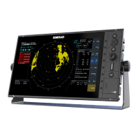
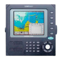
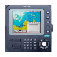
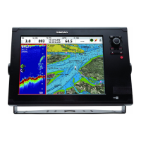
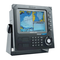
Overview of the primary radar control units and their features.
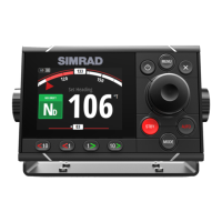
Description of the optional remote controller for radar units.
Introduction to examples of typical radar system installations.
Explanation of the function of each key and control on the front panel.
Details the Plan Position Indicator (PPI), target panel, and information indicators.
Customizing radar display elements like range rings and heading lines.
Status indicator showing if the display's live feed is active.
Explains softkey operations, pop-up displays, and their usage.
How to navigate through system menus and settings dialogs.
Changing units for distance and speed measurements in the system.
Choosing color schemes for radar video and target trails.
Using the virtual keyboard for data entry in dialogs.
How to take and save screenshots of the radar display.
Procedures for turning the radar system power on and off.
Adjusting screen brightness and selecting day/night color modes.
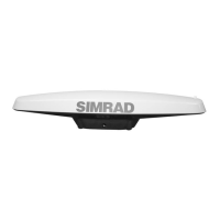
Choosing the active radar antenna and switching modes.
Adjusting display range and using the cursor for interaction.
Acquiring and managing radar and AIS targets.
Configuring speed input and system stabilization.
Adjusting radar receiver sensitivity for target visibility.
Reducing interference from weather and wave clutter.
Manually adjusting sea clutter settings for optimal performance.
Optimizing the radar receiver for maximum target returns.
Displaying historical target movement on the radar image.
Configuring display orientation: North-up, Head-up, Course-up.
Choosing between relative and true motion displays.
How true motion display works and how to reset it.
Adjusting the PPI origin point (Center, Look Ahead, Cursor).
Showing predicted target movement with speed and course.
Displaying cursor bearing relative to own vessel.
Resetting system controls to their default configurations.
Acquiring and selecting targets for tracking.
Setting CPA/TCPA limits for threat detection.
Steps to start tracking radar echoes using the cursor.
Icons used for different types of radar targets on the display.
Display settings for target trails and past positions.
Visualizing previous target locations and movement.
Factors affecting tracking accuracy and detection capabilities.
Displaying and managing Automatic Identification System (AIS) data.
Icons used for various AIS target types on the display.
Filtering AIS targets based on range and speed.
Details on how target data is displayed in the Target panel.
List of tracked targets and received AIS messages.
Setting up warning zones around the vessel for object detection.
Procedures for configuring guard zones (shape, alarm).
Tools for measuring distance and bearing to targets.
Interface for marker adjustment and selection of options.
Procedures for turning EBL/VRM markers on and off.
Detailed procedures for adjusting marker position and values.
Moving marker reference points for measurement.
Methods for taking measurements on the PPI using cursor/markers.
Using markers to measure distance from the vessel's origin.
Using markers to measure distance between two targets.
Preset control settings for different environments (Custom, Harbor, Offshore, Weather, Bird).
Adjusting minimum signal strength for radar target detection.
Reducing interference caused by other radar units.
Filtering out unwanted system noise to improve clarity.
Enhancing target visibility and size for easier identification.
Improving discrimination between closely spaced targets.
Increasing antenna rotation speed for faster target updates.
List of items included in the radar system package.
Advice on selecting a suitable and safe installation spot.
How viewing angle affects display visibility and clarity.
Procedures for mounting the unit using U-brackets.
Procedures for flush panel installation of the unit.
General advice for proper wiring installation and cable management.
Identification and description of rear panel connectors.
Information about the unit's Ethernet port for network connectivity.
How to connect the unit to a 12 or 24 VDC power source.
Managing system power states, especially for the R2009 unit.
Connecting the unit to an external alarm management system.
Establishing the NMEA 2000 network backbone for data communication.
Connecting various devices to the NMEA 2000 network backbone.
Designing the network layout and selecting components.
Providing appropriate power to the NMEA 2000 network.
Connecting devices via NMEA 0183 serial ports.
Details on specific serial cables used for NMEA 0183 connections.
Understanding serial data transmission roles and limitations.
Connecting an external monitor via HDMI for remote video output.
Overview of the necessary setup areas for system operation.
Adjusting radar specific parameters for optimal performance.
Defining vessel data for accurate system calculations.
Language, time, key beeps, and about information settings.
Restore defaults, file management, and advanced settings.
Setting up network connections and connecting to network devices.
Displaying connection status and assigning names to devices.
Choosing and configuring data inputs (Auto vs. Advanced).
Displaying connected data-providing devices on the network.
Tools for identifying and troubleshooting network issues.
Monitoring network status, bus state, and received message errors.
Monitoring communication errors and network traffic load.
Configuring NMEA 0183 communication parameters and baud rates.
Selecting transmitted data sentences via NMEA 0183.
Accessing and understanding radar configuration options.
Selecting the active antenna and checking radar status.
Positioning transceiver and calibrating radar range offset.
Aligning the heading marker with the vessel's center line.
Controlling transmission sectors and reducing sidelobe interference.
Initial tuning for optimal radar performance with large targets.
Setting antenna standby position and pedestal lighting levels.
Restoring original factory settings for the radar system.
Selecting color schemes for radar video and target trails.
Using demonstration mode and selecting data files for simulation.
Manual control of simulation parameters like GPS source and speed.
Choosing the origin of GPS data for simulation purposes.
Manually entering speed and course values for simulation.
Entering specific coordinates as the simulation starting point.
General care recommendations for maintaining the unit.
Cleaning display, port door, and checking keys/connectors.
Logging serial output data for service and fault finding.
Retrieving logged data from the system's file dialog.
Installing software updates and backing up system settings.
Categorizing alerts into Alarms, Warnings, and Cautions.
How alerts appear, are managed, and their states.
Procedures for clearing alerts from the Alerts panel.
Displaying active and historic alerts with timestamps.
A comprehensive list of system alerts and their types.
How system failures affect allowed or inhibited functions.
Definitions of technical terms and acronyms used in the manual.
List of optional items and accessories for the R2009 unit.
List of serviceable parts and kits for the R2009 unit.
List of optional items and accessories for the R3016 unit.
List of serviceable parts and kits for the R3016 unit.
Summary of key technical data for both R2009 and R3016 units.
Details on screen size, resolution, and display type.
Operating conditions, waterproof ratings, and standards compliance.
Electrical requirements and power usage of the units.
Minimum distances required to avoid magnetic interference.
Visual representation of main and sub-menu paths for system navigation.
Physical dimensions and mounting details of the R2009 unit.
Physical dimensions and mounting details of the R3016 unit.
| Display Type | LCD |
|---|---|
| AIS Compatibility | Yes |
| Display Size | 9 inches |
| Chart Compatibility | Navionics |
| Power Supply | 12/24V DC |
| Mounting | Flush mount |
| Compass | Not included |
| Networking | NMEA 2000 |
| Weight | 1.8 kg |
| Resolution | 480 x 800 pixels |