Installation
20220752G 23
Note !
1. If one or two more instruments are added to the above
system the Wind Transducer must be connected to the no. 2
connector on the last instrument in the chain.
2. Boat speed input is required to display True Wind angle and
speed. The above system needs speed input on NMEA 0183
format. To display magnetic wind direction also heading
input is required together with speed from the same source
or from a separate NMEA source via a second instrument.
3. When connected to an IS15 Tri-data system as shown on
Figure 5-4 speed is available on Roblink format and heading
on NMEA format.
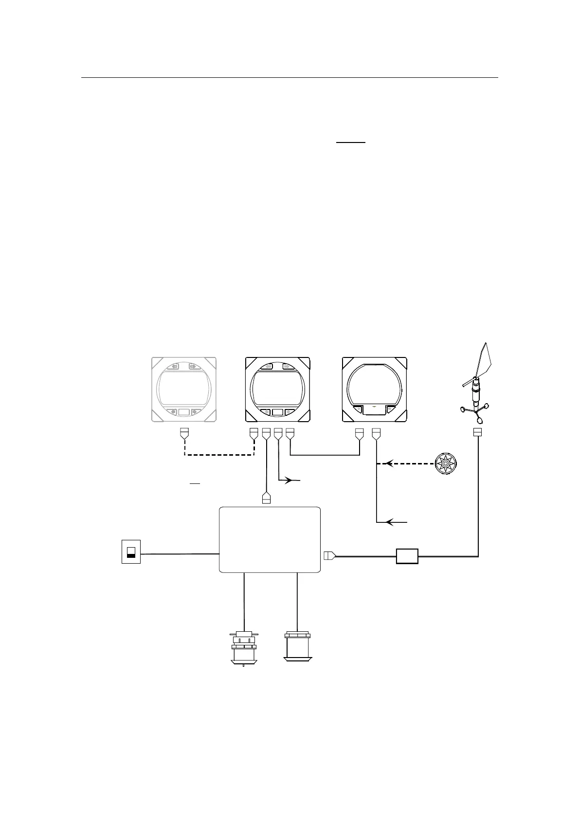
Integrated systems
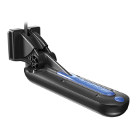
Speed/temp
transducer
Depth
transducer
Supply 10,8-15,6VDC
SIMRAD
IS15 Combi/Multi
10 m (33')
10 m (33')
10 m (33')
IS15
Transceiver
SIMRAD
0,3 m (1')
IS15 Combi/Multi
Wind
Transducer
IS15 Wind
SIMRAD
Junction box (mast foot)
0,3 m (1')
10 m (33') 30 m (99')
From Autopilot
(NMEA)
Stand alone
compass
NMEA
To Autopilot
(NMEA)
NOTE:
The wind transducer should be
connected to the Transceiver unit.
NOTE:
Cables are
not shown
in connected order.
Circuit breaker
Optional
third
instrument
*
*
*
*
**
**
Denotes Roblink
cable with connector
Optional extra cable
*
**
Figure 5-4 IS15 Wind – IS15 Combi (Tri-data) System layout
An example of a fully equipped IS 15 system is shown in Figure
5-5. See also the Interconnection – Principle diagram Figure 6-5
in the IS15 General Manual.