1 2 3 4
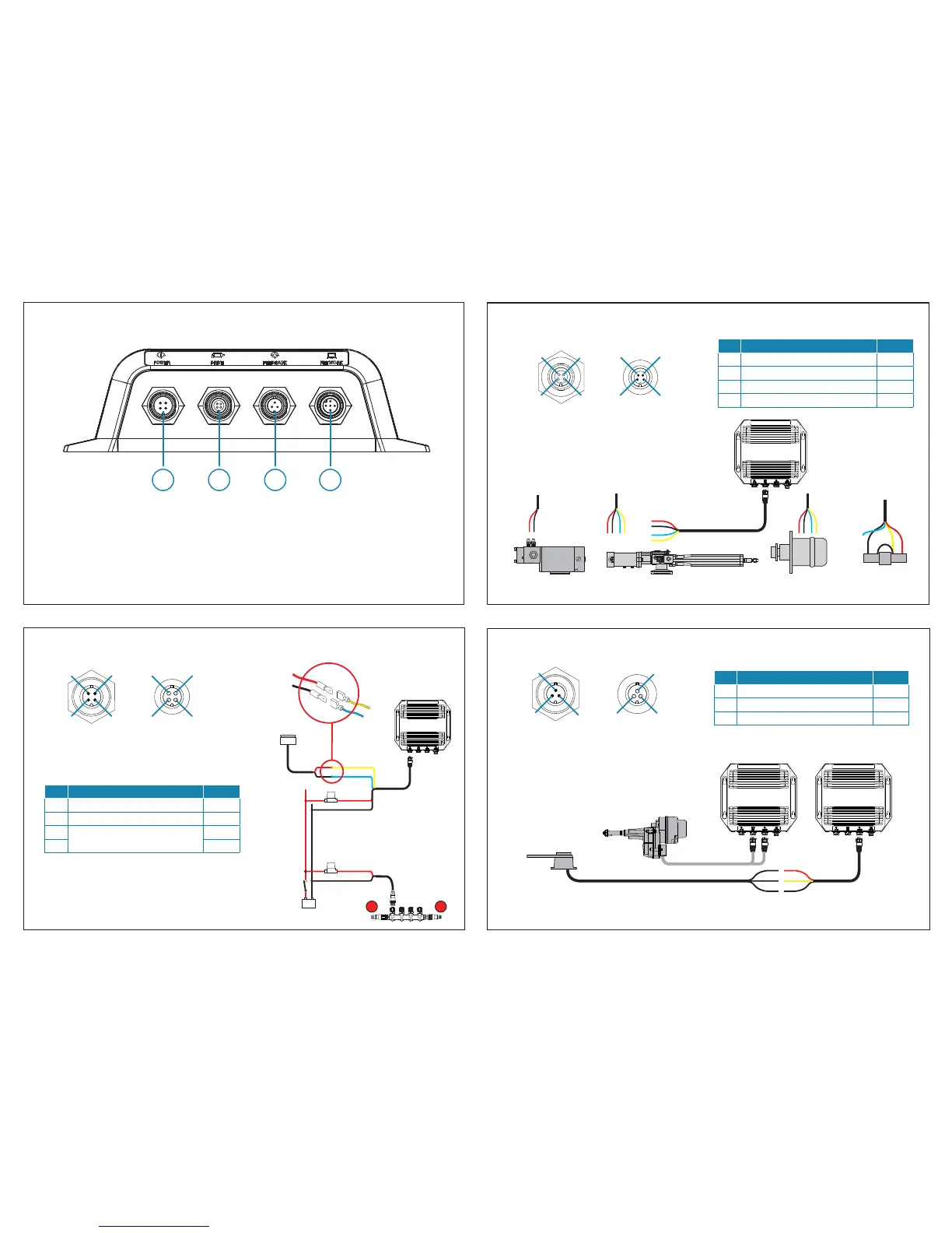
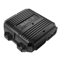
Connectors & Wiring
+
_
12 V DC
MAIN
POWER
SWITCH
0.9 m (3 ft)
FUSE,
20 AMP
2 m (6 ft)
1 m (3 ft)
T T
OPTIONAL
AUTO/STBY
BUTTON
RED
BLACK
YELLOW
BLUE
Key Function Color
1 - 0V DC
Black
2 + 12 / 24V DC Red
3
Auto/ Standby button (Optional)
Yellow
4 Blue
1
4
2
3
3
2
4
1
Power
Socket Plug
1. P
ower (12 / 24 V DC)) - Max 8A/12A Continuous/Peak
2. Drive (Drive unit) - Max 8A/12A Continuous/Peak
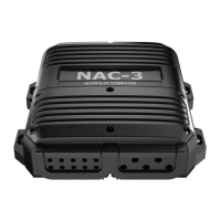
3. Feedback (Rudder reference - Resistive feedback units only)
4. Network (NMEA 2000)
Resistive
Rudder feedback
unit
Key Function Color
1 + 5V DC
Red
2 Signal Yellow
3 - 0V DC Black
Feedback
Socket Plug
3
1
1
3
2
2
Drive (Max 8A/12A Continuous/Peak)
Reversible pump
Hydraulic linear drive
Rotary drive Solenoid valve
Key Function Color
1 Clut
ch GND/Solenoid Common Yellow
2 Clutch Blue
3 Motor_A Red
4 Motor_B Black
Socket Plug
1
2
3
4
4
3
2
1
Auto/Stby button (optional)
Note: Navico NMEA 2000 Rudder feedback units should be connected directly to the NMEA 2000 backbone.
Helm-1 Combined
Drive &
Rudder feedback
unit
Example 1 Example 2