| 27
Operation | NAIS-500 User Manual
Indicator functions
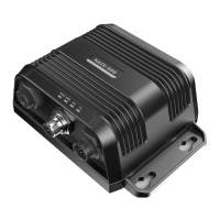
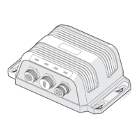
The AIS transceiver includes four LED indicators, as shown in Figure
13. The state of the indicators provides information regarding the
status of the AIS transceiver.
Indicator lights
Green Amber Red Blue
Figure 13 Indicator location on the AIS transceiver unit
The meaning of typical indicator configurations is shown in the table
below and Figure 13 shows the orientation of the AIS transceiver.
Indicator
Light Description
PWR Green, steady The transceiver has been powered up correctly.
ERR Red, steady MMSI is not properly programmed.
Red, flashing The transceiver has detected a system error. Also the state when
connected to USB only for initial programming.
Rx Green, flashing The transceiver is receiving AIS data.
Tx Orange,
flashing
The transceiver is acquiring a GPS fix, no AIS transmission during
this time period.
This can be the following situation:
The device is just newly powered on and is acquiring a GPS
position fix prior to transmitting its first vessel information
report. This process may take several minutes.
The GPS position fix has been lost. The device is attempting
to re-acquire position fix for 30 minutes before entering a BIIT
system error state.
Orange, steady The transceiver is in silent mode, no AIS transmission at all.
Green, flashing The transceiver is transmitting AIS data.
The flash interval is 3 minutes when vessel speed under 2 knots.
The flash interval is 30 seconds when vessel speed above 2
knots.