Adjust antenna height
Set the radar scanner height relative to the water surface. The Radar uses this value to
calculate the correct STC settings.
Select antenna length
Select the proper antenna length.
Adjust range offset
The radar sweep should commence at your vessel (a radar range of zero). You may need to
adjust the radar range offset to achieve this. If this is set incorrectly, a large dark circle in the
center of the sweep might occur. You might notice straight objects such as straight sea walls
or piers having curves or an indentation. Objects close to your vessel may appear pulled in or
pushed out.
Adjust the range offset as below when the vessel is about 45 to 90 m (50 to 100 yards) from a
straight-walled jetty or similar feature that produces a straight line echo on the display.
1 Point the vessel towards the jetty
2 Adjust the range offset to make the jetty echo appear as a straight line on the
display
Adjust bearing alignment
This option is used to align the heading marker on the screen with the center line of the
vessel. This will compensate for any slight misalignment of the scanner during installation.
Misalignment that is not corrected for will compromise target tracking and can result in
dangerous misinterpretation of potential navigation hazards.
Any inaccuracy will be evident when using MARPA or chart overlay.
1 Point the vessel towards a stationary isolated object, or towards a far range AIS
where the AIS icon matches the radar echo
2 Adjust the coarse and fine bearing alignment so that the heading line touches the
end of the selected object
Sidelobe suppression
Occasionally false target returns can occur adjacent to strong target returns such as large
ships or container ports. This occurs because not all of the transmitted radar energy can be
focused into a single beam by the radar antenna, a small amount of energy is transmitted in
other directions. This energy is referred to as sidelobe energy and occurs in all radar systems.
The returns caused by sidelobes tend to appear as arcs.
Ú
Note: This control should only be adjusted by experienced radar users. Target loss in
harbor environments may occur if this control is not adjusted correctly.
When the radar is mounted where there are metallic objects near the radar, sidelobe energy
increases because the beam focus is degraded. The increased sidelobe returns can be
eliminated using the sidelobe suppression control.
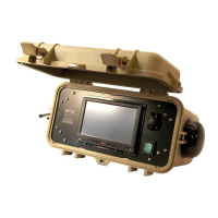
Software setup | NSO evo3S MPU Installation Manual

 Loading...