| 23
Installation | RS90 Installation Manual
Connector 1 - Fuse
Install a 10 Amp MINI® blade fuse.
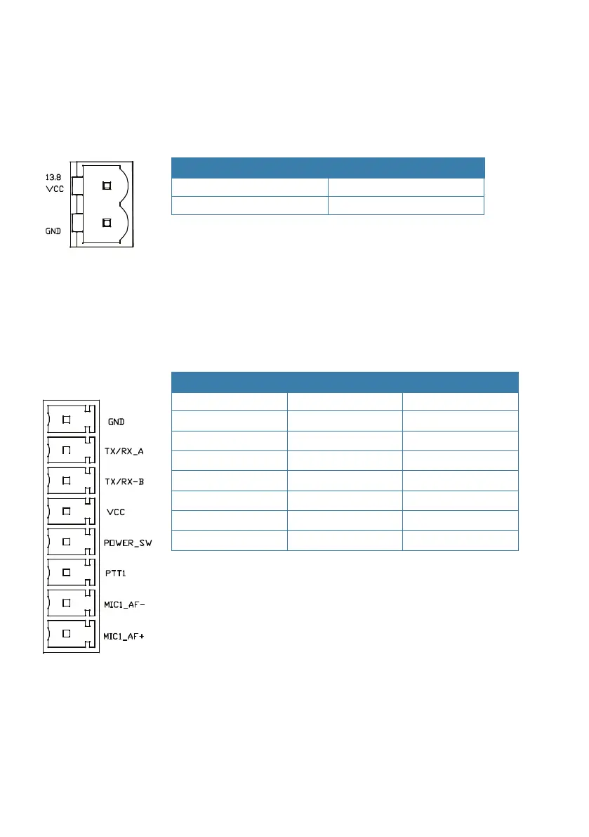
Connector 2 - Power connection
Label Wire colour
VCC Red
GND Black
¼ Notes:
• Voltage: 12 VDC (10.8 VDC to 15.6 VDC)
• Ground must be connected to the vessel’s common ground,
which must be negative.
Connectors 3, 4, 5 and 6 - Wired handsets
Number Label Wire colour
1 GND Black
2 TX/RX_A Blue
3 TX/RX_B Green
4 VCC Red
5 POWER-SW White
6 PTT Grey
7 MIC_AF- Yellow
8 MIC_AF+ Orange
¼ Notes:
• All the necessary wires are included in the handset cable
supplied.
• The wired handset cable includes a connector assembly that
must be installed in a bulkhead, dashboard or other suitable
panel. See page 18.