| 25
Installation | RS90 Installation Manual
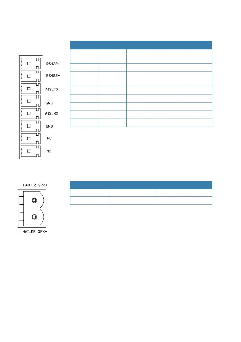
Connector 9 - AIS Data Output
(NMEA 0183HS 38400 bps )
Number Label Description
1
RS422+ Output+ (RS-422 type)
AIS RS422 data output only
2 RS422- Output- (RS-422 type)
3 AIS_TX Output+ (RS-232 type)
Connect to PC or chart plotters
4 GND Output- (RS-232 type)
5 AIS_RX Not used
6 GND Not used
7 - -
8 - -
Connector 10 - Loud hailer speaker
Number Label Description
1 HAILER SPK+
2 HAILER SPK-
Important: Do not short circuit these 2 connectors.
Install the hailer speaker in a forward-facing location on the boat.
This is because, in addition to transmitting foghorn sounds, the
hailer speaker ‘listens back’ when not transmitting.
¼ Note: Use a 4-8 ohm speaker or loud hailer horn rated at no less
than 30 W. Higher impedance will reduce audio output volume.
Connector 11 - programming connector
This is a Micro-USB receptacle used for factory diagnostic purposes.