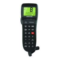
3.2 Electrical Installation
The RT62/64 has four electrical connections - the handset/fist-
mike socket is on the front panel below the LCD display (Fig
3.4A). The other three are situated on the back of the case - the
antenna socket is on the right (Fig 3.4B), a 3.5mm jack socket
for an optional extension speaker on the left (Fig 3.4C), below
which is the DC power input via a two core flying lead (Fig
3.4D). An earth stud (Fig 3.4E) is provided to earth the case.
Instruction Manual
19
E04074
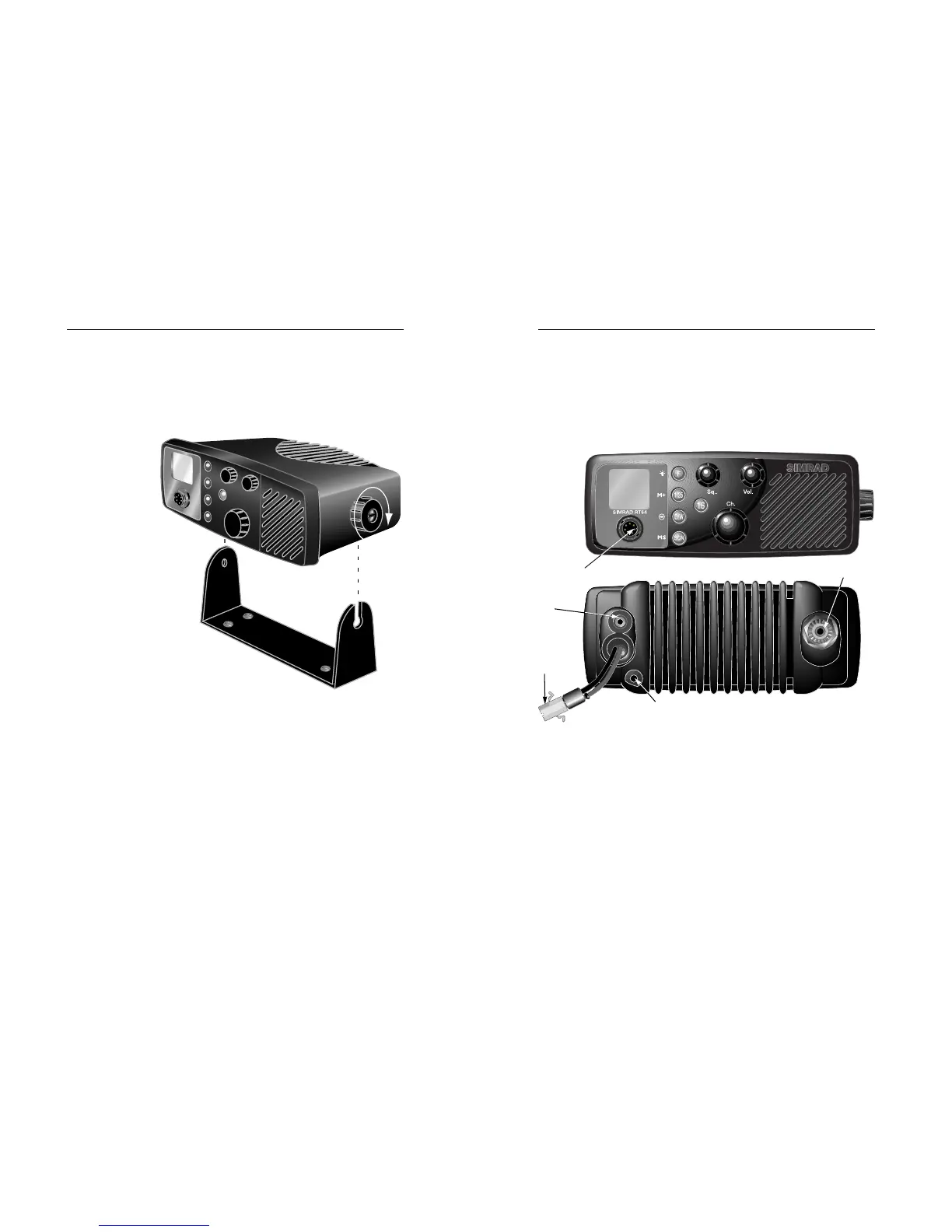
The radio is fixed to the bracket using a simple clamp arrange-
ment. The peg on the left side of the radio is slotted into the
hole in the bracket. The clamp on the right side of the radio
can then be slid into the slotted aperture on the bracket and
tightened to hold the radio firmly in place (Fig 3.3). The rake
angle of the radio can be adjusted by slackening the clamp.
RT62 & RT64
18
E04074
1. Fit locating peg (left side) into hole in bracket
2. Slide locking clamp (right) into slot in bracket
3. Tighten clamp
Fig 3.3 - Fixing VHF to bracket
1
2
3
An alternative mounting method is to use the flush mounting
kit FMB1000BK (supplied separately). This allows the radio to
be neatly installed inside a bulkhead, so that only the fascia of
the radio is visible. For more details of this and other acces-
sories available, please refer to section 4.1.
A - Handset/
Fistmike
B - Antenna
D - 12v DC
C -
Extension
Speaker
The radio requires a 12v DC supply, and is supplied with a
power lead which incorporates an in-line 7.5 amp fuse. This
lead should be connected to the vessel’s power supply, keep-
ing the cable runs as short as possible. Although the radio
draws little current when receiving, a heavier current is drawn
when transmitting which may result in a voltage drop if very
long cable runs are used of inadequate core diameter. If the
supplied power lead is not long enough, an extension of up to
3m (10 ft) can be made using at least 2.5mm2 (13AWG) wire.
The red wire is positive and black is negative. If polarity is
accidentally reversed, the set is protected but the fuse will
blow. Ensure that it is replaced with a fuse of the correct 7.5
amp rating. The radio is designed to be easily removable for
E - Earth Stud
Fig 3.4 - External connections