Sinclair ZX Spectrum Service Manual
Spectrum For Everyone https://spectrumforeveryone.com/
18
a space in response to the START signal from the Z80. In this case the PIC and Z80 determine that the
next START signal is a call for the result of the row scan at the next column address. If the scan indicates
that there has been a change in status since the previous scan, the PIC responds positively by sending a
mark in response to the START signal. The Z80 responds by sending a further four START signals,
prompting the PIC to transmit a 4-bit serial code with a ‘1’ set in the bit position corresponding with the
particular row. Since the Z80 keeps a log of the column address by counting the number of START signals
it sends and registering the PIC responses since the start of the interrupt, it can readily identify the key
code from a look-up table.
On a physical level, data exchanges between the PIC and the Z80 are conducted at RS232 signal levels
over a single line pair - a transmit line (TXD/RXS) from the Z80 to the PIC and a receive line (CTS/TXS)
from the PIC to the Z80. The transmit signal, originated by the Z80, is output as bit AO from the Port A
Data Store in the sound generator IC32 during a write to I/O address BFFD
H
. From IC32 the data is
converted from logic to RS232 levels in IC33 and routed from there to the PIC. A 4.3V Zener diode on the
keypad receive line, limits the positive signal excursion (space) to +4.3V and the negative signal
excursion (mark) to 0V.
The transmit signal, originated by the PIC, follows a reciprocal path and is input to the Z80 from the
sound generator as bit A5 in the Port A Data Store during a read from I/O address FFFD
H
(NOTE: The
RS232C receiver IC34 recognises a mark as 0V and a space as any level exceeding +3V).
Accesses to the Port A Data Store are identical to those described under the heading ‘RS232/MIDI
Interface’.
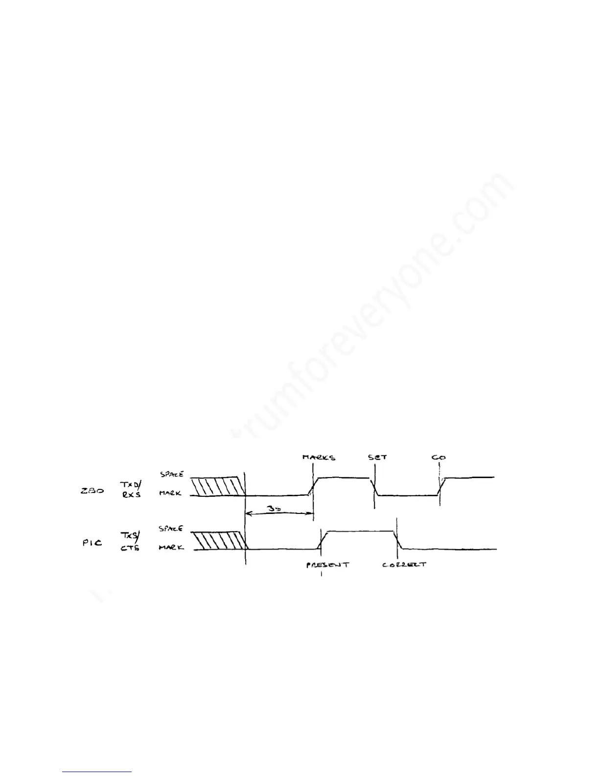
1.9.1 Reset Protocol
The synchronising sequence which runs after power up or reconnection (as seen at the RS232
connector) is shown below:
The significant time delays are as follows:
a) The initial 3 second delay which ensures that the PIC is up and running. During this time the
keypad is inoperative.
b) The 1ms delay between the Z80 setting TXD high (MARKS) and the PIC responding by setting TXS
high (PRESENT). If the delay is exceeded, the Z80 assumes that some other device is connected,
and abandons the reset sequence.
 Loading...


