User Manual of A90 Series Inverter
225
F13.01=1:AI1
F13.01=2:AI2
The torque is dependent on AI (percentage) * F13.02.
F13.01=6: communication setting
The torque depends on the communication and the like.
If the master-slave communication (F10.05=1) is enabled and the inverter works
as the slave (F10.06=0), the specific setting percentage is “700FH (master-slave
communication setting) * F10.08 (slave receiving proportional coefficient)”, and
the 700FH data range is -100.00% to 100.00%, as detailed in Table 0-2.
For the general communication (F10.05=0), the specific setting percentage is “7003H
(torque communication setting) * F13.02 (digital torque setting)”, and the 7003H data
range is -200.00% to 200.00%, as detailed in Table 0-2.
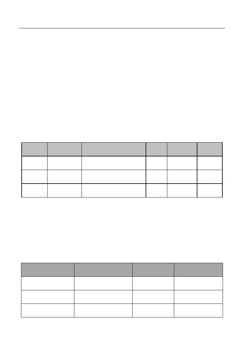
For diversified torque applications, the A90 series inverter supports the multi-segment
torque function. Specifically, the input terminal functions “17: multi-segment torque
terminal 1” and “18: multi-segment torque terminal 2” need to be set. See the instruction
Table 7-19 for details.
Table 7-19 Combination of Multi-segment Torque Command and Multi-segment Torque
Terminal
18: multi-segment
torque terminal 2
17: multi-segment torque
terminal 1
Depending on the
F13.01 setting
 Loading...