User Manual of A90 Series Inverter
232
Terminals”.
Time t
Output
frequency
0
Fundamental
frequency of
acceleration and
deceleration time
F15.09
Set deceleration
time
Set acceleration
time
Actual
acceleration time
Actual deceleration time
Set frequency
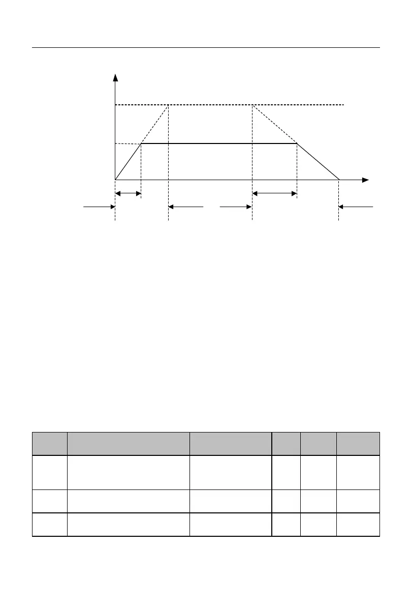
Fig. 7-32 Schematic Diagram of Acceleration and Deceleration Time
As shown in Fig. 7-32, the acceleration time is defined as the time of acceleration from
0.00 Hz to the reference frequency of acceleration/deceleration time; and the deceleration
time is defined as the time of deceleration from the reference frequency of
acceleration/deceleration time to 0.00 Hz. The actual acceleration/deceleration time varies
according to the ratio between the set frequency and reference frequency.
The reference frequency of acceleration/deceleration time is set by function code
F15.09 that represents the reference frequency of acceleration/deceleration time. If
F15.09=0, the reference frequency depends on the function code F00.16 (maximum
frequency). Assuming F00.16=100.00Hz, the acceleration (deceleration) time is expressed
as the time for the output frequency to increase (decrease) from 0.00Hz (100.00Hz) to
100.00Hz (0.00Hz).
Automatic switching of
acceleration and deceleration
time
Switching frequency of
acceleration time 1 and 2
0.00 to maximum
frequency F00.16
Switching frequency of
deceleration time 1 and 2
0.00 to maximum
frequency F00.16
 Loading...