Note: 1): Products of AC220V, 4.8A - 6.2A apply to single-phase and three-phase AC220V power
supply, so there is no special single-phase AC220V product.
2): For products of AC 220V, 11A and above, only the ones applicable to three-phase AC 220V
power supply are provided.
3): For products of AC 220V, 2.5A and below, only the ones applicable to single-phase AC
220V power supply are provided.
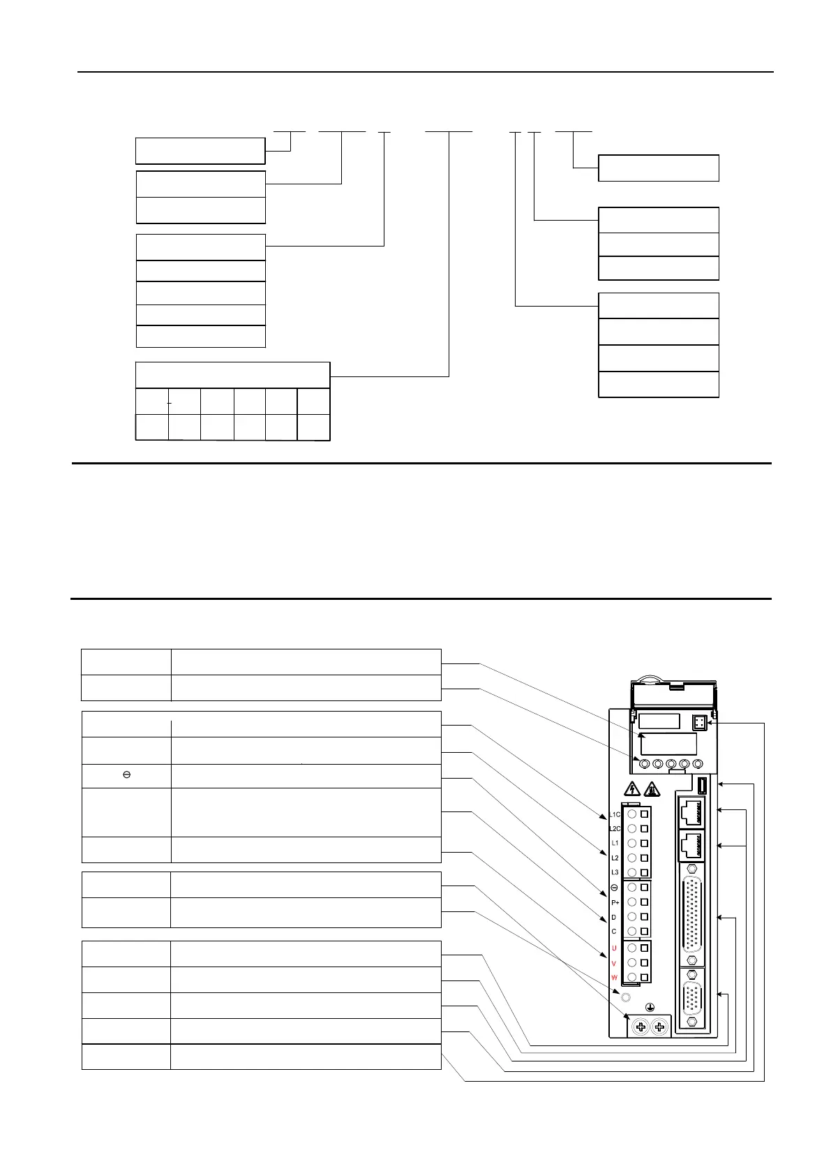
LED display
Buttons
CHARGE Bus voltage
indicator lamp
L1C, L2C control
circuit power supply
L1, L2, L3 main circuit
power supply
P+,
P+, D, C
external braking resistor
CN5 encoder
connection terminal
PE grounding
terminal
5-bit 7-segment LED displays running state
Parameters
setting
Used to indicate whether the bus capacitance is in a charged state. When the
lamp is on, the capacitor inside the drive is charged even if the main circuit
power supply is OFF.
Refer to the nameplate
Refer to the nameplate (Size A model, i.e. 0R9, 1R6, 2R5 models have no
L3 terminal)
DC bus voltage terminal, for DC bus sharing
A short connector is installed between P+ and D by default; when using
external braking resistor, remove the short bar to create open circuit between P+
and D, and connect an external braking resistor between P+ and C. (Size A
model, i.e. 0R9, 1R6, 2R5 models have no D terminal)
Connected to servo motor U, V, W
Connected to the encoder of servo motor
Connected to power supply and servo motor ground
Connected to the upper controller
CN4 control terminal
CN2, CN3
comm terminal
Two in parallel, including RS232, RS485, CAN comm. port
CN6
USB comm. port
USB comm. port reserved
U, V, W
Servo motor
CN1 analog
Monitoring port
Two analog outputs
 Loading...
