What to do if there's fault wiring or a short circuit in the Sinfonia Technology Controller?
- MMichelle HendersonAug 1, 2025
Unfortunately, there is no specific solution provided in this manual extract to resolve fault wiring or short circuits.

What to do if there's fault wiring or a short circuit in the Sinfonia Technology Controller?
Unfortunately, there is no specific solution provided in this manual extract to resolve fault wiring or short circuits.
What to do if the weight of the bowl or chute is too heavy for the Sinfonia Technology Controller drive unit?
If the bowl or chute is too heavy, reduce the weight by decreasing the thickness of the bowl or chute. You may also need to adjust the air gap.
What to do if there is fault wiring, confusing polarities, or the air gap is out of standard width in the Sinfonia Technology Controller?
Review the wiring plug connector. Additionally, narrow the air gap of the core and armature of the drive unit.
How to adjust the resonant frequency of the Sinfonia Technology Controller?
Review the function setting. Readjust the resonant frequency of the drive unit with leaf springs.
Why is the drive frequency range out of the resonant frequency of the drive unit in Sinfonia Technology Controller?
Unfortunately, there is no specific solution provided in this manual extract to resolve this problem.
What to do if there is a fault function setting for the Stroke Sensor of Sinfonia Technology Controller?
Unfortunately, there is no specific solution provided in this manual extract to resolve this problem.
What to do if the feeder provides a bowl out of the specification for Sinfonia Technology Controller?
Unfortunately, there is no specific solution provided in this manual extract to resolve this problem.
| Brand | Sinfonia Technology |
|---|---|
| Model | C10 Series |
| Category | Controller |
| Language | English |
Identifies the specific models covered by the manual.
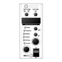
Details the buttons, lamps, and dials on the controller's front panel.
Emphasizes the importance of reading safety instructions before use.
Provides crucial safety warnings and classifications (Danger, Warning, Caution, Request).
Highlights immediate hazards that can cause serious injury or death.
Points out indirect dangers that can cause injury or property damage.
Warns of potential minor injury or property damage from misuse.
Offers recommendations for proper use and handling of the controller.
Lists specific hazardous actions to avoid with the C10-controller.
Details warnings related to electrical power, operation range, and physical handling.
Lists precautions for installation, maintenance, and operation environments.
Provides guidance on handling unusual conditions and disposal.
Instruction to safely remove the control panel before wiring.
Details connecting power, output, and sensor cables to terminals.
Instruction to secure the control panel after wiring.
Describes each component on the control panel and its purpose.
Guides the user on starting and stopping the partsfeeder using the panel.
Explains causes and remedies for the RUN lamp blinking.
Step-by-step guide to setting the stroke parameter.
Explains how to store the adjusted settings.
Guides on selecting function codes and modifying their values.
Instructions on saving the modified function set values.
How to select the correct drive frequency range for the partsfeeder.
Adjusting the stroke for optimal parts discharge.
Configuring maximum stroke and scaling parameters.
Overview of supplementary functions available.
Basic steps for daily operation.
Choosing the appropriate frequency range for the connected feeder.
Detailed steps to set stroke parameters using auto-tuning mode.
Adjusting stroke value in constant voltage mode.
Storing the configured stroke value.
Adjusting stroke value in constant stroke mode.
Selecting frequency after setting stroke in constant stroke mode.
Running the feeder and fine-tuning stroke.
Saving the final stroke adjustment.
Setting initial stroke and selecting the scaling function.
Adjusting the coefficient for scaling the stroke.
How to enable and use the keylock function to prevent unauthorized changes.
Configuring delay times for overflow and other functions.
Adjusting the time taken for the feeder to reach operating speed.
Details the wiring for the overflow sensor.
Wiring diagram and notes for the stroke sensor.
How to use P1/P2 terminals for running and stopping.
Details synchronous output signals and auxiliary outputs.
How to control speed using current or rheostats.
Identifies the physical location of relevant connectors on the PCB.
Step-by-step guide to saving speed change configurations.
Instructions on how to disconnect cables from the E-Con connector.
Guidelines for installing the controller in an enclosure.
Initial checks to perform when troubleshooting.
Specific troubleshooting steps for when the feeder fails to run.
Steps to resolve issues with stroke buildup and fluctuations.
How to fix issues where settings are not stored.
 Loading...