5
HTE302172
29/46
6
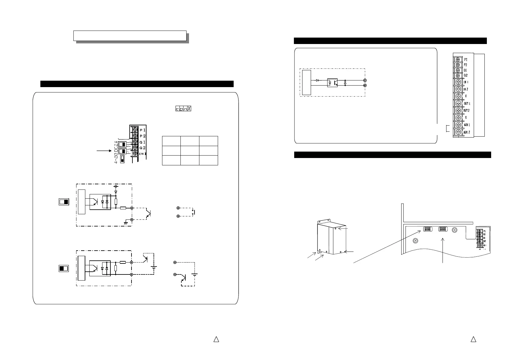
Please wire the external signal terminals as the drawing in the columns below for frequent
running and stopping, taking out synchronous signal with running and stopping and speed
change of a partsfeeder.
○
Dry contacts or an open collector
Inner Circuit
P2
P1
2.2KΩ
P
1
1
1
1
2
2
2
2
DC24
P1
P2
※ Be careful for the polarity
of the external signal using
a semi-conductor switch.
+12V
○
External voltage
Inner Circuit
P1
P2
2.2KΩ
P
1
1
1
1
2
2
2
2
DC24
P1
P2
DC12~24V
DC12~24V
※ Connection P1,P2 are reversible.
Logic of the external
contacts open or close
X 0 1
Open Run Stop
close
Stop Run
How to use External Signal Terminals
How to use External Signal TerminalsHow to use External Signal Terminals
How to use External Signal Terminals
External Operation Signal Terminals P1 and P2
External Operation Signal Terminals P1 and P2External Operation Signal Terminals P1 and P2
External Operation Signal Terminals P1 and P2
Logic is reversible by Function
code “ ”. “X” is set
for “0” or “1”.
☆R
RR
Running and stopping with an external signal
unning and stopping with an external signalunning and stopping with an external signal
unning and stopping with an external signal
Close or open the terminals P1 and P2 respectively
with an external relay with dry contacts or an open
collector.
Factory Default
Select control by 4-20mA
current or Two-rate-of-feed
with a slide switch on
the print circuit board.
5
HTE302172
30/46
6
The right side socket
The right side socketThe right side socket
The right side socket
connector
connector connector
connector “
““
“E
EE
E-
--
-Con1
Con1Con1
Con1”
””
” is
used for speed change and error signal output.
The connector must be connected to one of two connectors
named “4321” on the printed circuit board.
The
TheThe
The
left side socket connector
left side socket connector left side socket connector
left side socket connector “
““
“E
EE
E-
--
-Con2
Con2Con2
Con2”
””
” is used for
control by 4 -20 mA current or two-rate-of-feed by two
external rheostats.
To use those functions an output or input cable must be connected with a special plug
connector model “XN2A-1430 by OMRON that is provided by customer.
Remove the panel and a side cover.
E
EE
E-
--
-Con1
Con1Con1
Con1
E
EE
E-
--
-Con2
Con2Con2
Con2
Location of the Connectors
Location of the ConnectorsLocation of the Connectors
Location of the Connectors
Warning! :
Warning! :Warning! :
Warning! : Before remove the control panel, disconnect and lock out the power supply at
the safety disconnect switch.
Caution! :
Caution! : Caution! :
Caution! : Fault connection of “E-Con1” and “E-Con2” should damage C10-controller.
There is no indication of “E-Con1” or “E-Con2” on the printed circuit board.
The connector must be connected to
one of two connectors named
“E-Con” on the printed circuit board.
Speed change/Control by 4
Speed change/Control by 4 Speed change/Control by 4
Speed change/Control by 4
20 mA current/Two
20 mA current/Two20 mA current/Two
20 mA current/Two
feed control by external
feed control by external feed control by external
feed control by external
Rheostats
Rheostats Rheostats
Rheostats
Operation Synchronous Signal Terminals Q1 and Q2
Operation Synchronous Signal Terminals Q1 and Q2Operation Synchronous Signal Terminals Q1 and Q2
Operation Synchronous Signal Terminals Q1 and Q2
The terminal Q1 and Q2 outputs the synchronous signal with
running and stopping of the partsfeeder.
The output transistor closes
when a partsfeeder is running.
Maximum output voltage: DC 24 V
Maximum output current: 80 mA
LED「RUN」
Q1
Q2
Operation Synchronous power output
Operation Synchronous power output Operation Synchronous power output
Operation Synchronous power output terminals
terminalsterminals
terminals
AUX. OUT
AUX. OUTAUX. OUT
AUX. OUT
The terminals, AUX1 and AUX2, output power supply
synchronous with operation of the partsfeeder.
Output voltage: The same as the input voltage to
C10-controller
Maximum current: 2A
Operation Synchronous Signal Terminals Q1 and Q2, and AUX. OUT
Operation Synchronous Signal Terminals Q1 and Q2, and AUX. OUTOperation Synchronous Signal Terminals Q1 and Q2, and AUX. OUT
Operation Synchronous Signal Terminals Q1 and Q2, and AUX. OUT
AUX OUT(2A)
Inner Circuit
4321
4321
 Loading...