5
HTE302172 21/46
6
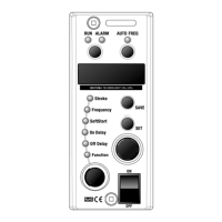
5. Dial the “Setting Encoder” to set the output frequency so that “ALARM” lamp is not turned on.
The output frequency is generally adjustable manually within 3% against the auto-tuned.
6. Push “Save” button to save the data having been set.
Push button Storing New data is stored
Setting Encoder
Dial
When the stroke is hunting on the constant stroke mode
reduce the gain on the Function code “G”.
5
HTE302172 22/46
6
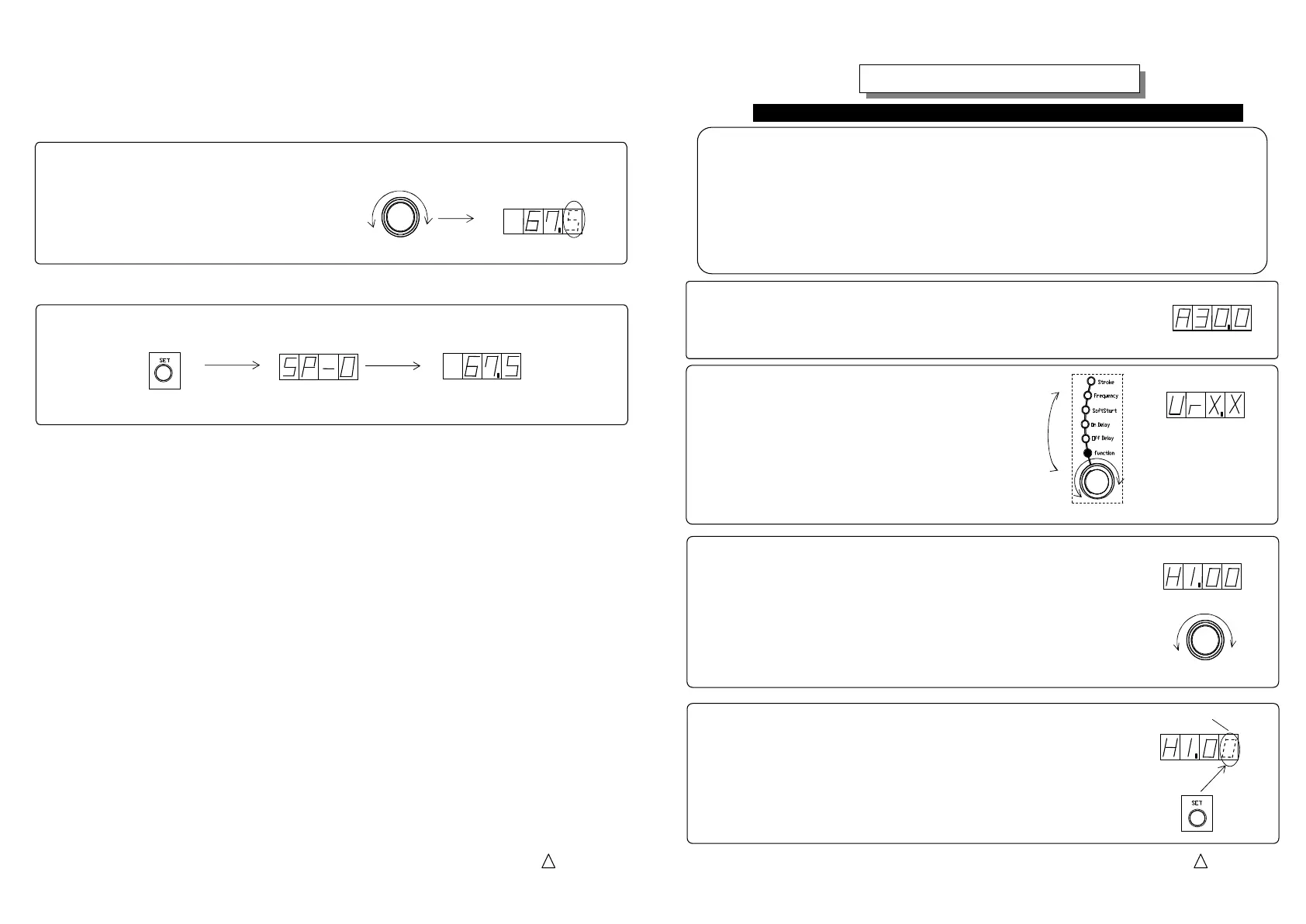
4. Push “Set” button to change the mode from “Indication” to “Adjust”.
The second decimal place of the scaling coefficient blinks.
Another push enables to change the first decimal place.
Note: Dial the setting encoder to set a new coefficient or to reset old
one to the original “1.00”.
Initial Setting
Initial SettingInitial Setting
Initial Setting
Scaling of the stroke
Scaling of the strokeScaling of the stroke
Scaling of the stroke
1. Adjust and set the “Stroke” on the usable maximum stroke of the bowl or chute.
Note: The stroke must be set within the maximum stroke of the drive unit.
2. Dial the selection dial and select the function turning
on “Function” lamp.
Function data appears
Selection Dial
Dial
Turning on
3. Dial the setting encoder up to appear function cord “H” for a scaling coefficient.
The scaling coefficient appears on the display.
The scaling coefficient means a proportionality constant
that converts a stroke data into the controllable range.
Example: Original stroke data “30.0” percent per the output voltage
Alter the scaling coefficient 1.00 to 2.00 and then
Stroke data converted “60.0” percent per the controllable range
Blinking
Changeable
Push
Scaling of the stroke converts usable stroke range into controllable range as 0 to 100%.
The usable stroke range is from the minimum to the maximum stroke set in the former procedure.
Before scaling the stroke, the value means a percentage per the output voltage of controller but
after scaling, the value means a percentage per the controllable range.
A CF drive unit, control by 4-20mA current and control by two-rate-of-feed must require the scaling.
The scaling must be done on the setting of combination No. 0, Speed change signal, and function
cord “rnt 0”, Control by Panel.
Note: No scaling is done on the other setting such as combination No. 1, 2 and 3 and/or function
-Continued-
maximum stroke data
Dial
Setting Encoder
 Loading...