11
3.2 Signal connector (X5)
One or more of the following functions are available, depending of the product
model:
Relay output 1: Volt free SPDT contact, max. load 5 A @24 V AC/DC
Relay output 2: Volt free SPDT contact, max. load 5 A @24 V AC/DC
Analogue output: 4-20 mA, active,isolated. Isolation Voltage 500 V.
Serial communication: RS-485 isolation Voltage 500 V.
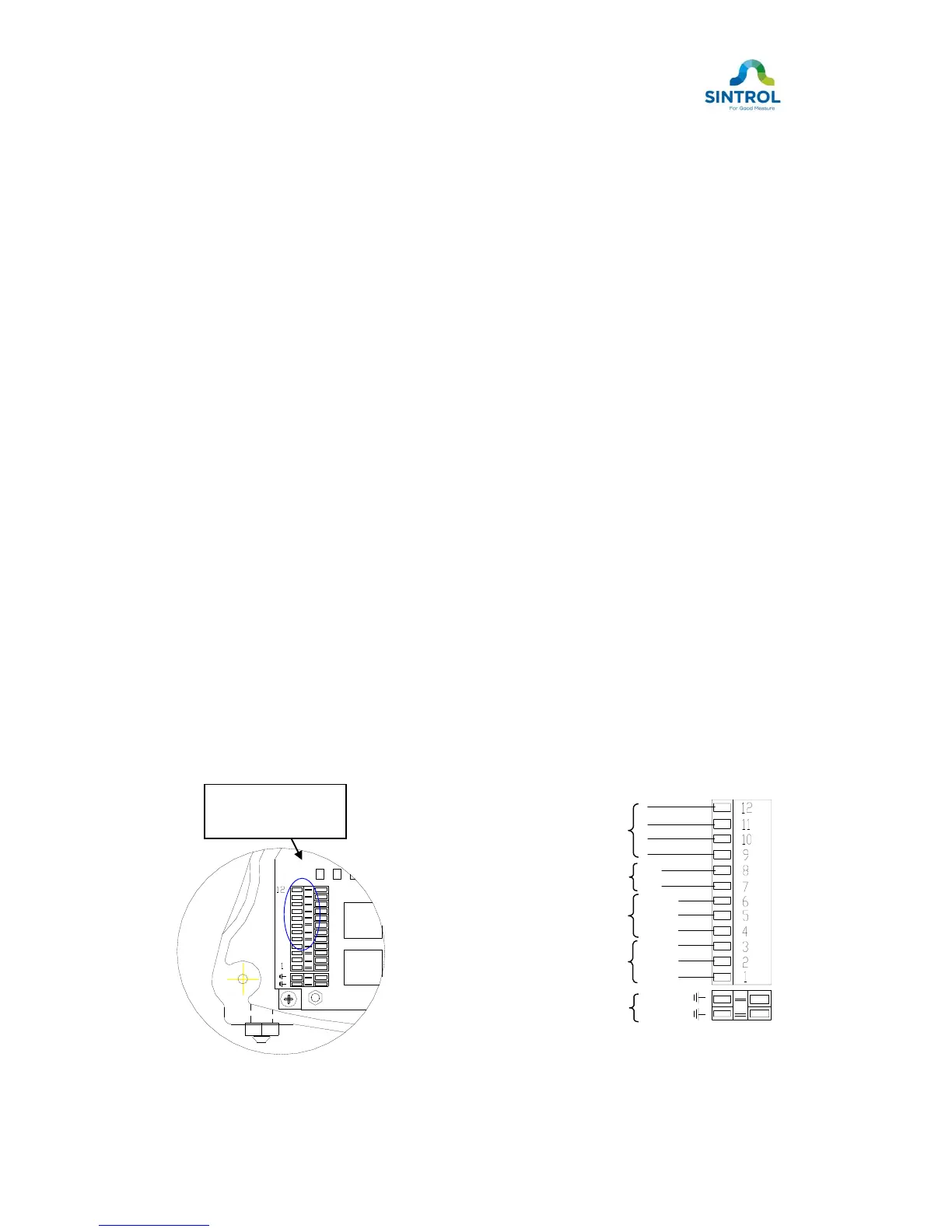
Connect the signal wires to connector X5 (see Figure 5a and 5b). Push the
connector lever with a screw driver, until the connector slot jaw opens, insert or
remove the wire, then release the lever.
Slot 1 Relay1 normally closed (NC) terminal.
Slot 2 Relay1 common (C) terminal.
Slot 3 Relay1 normally open (NO) terminal.
Slot 4 Relay2 normally closed (NC) terminal.
Slot 5 Relay2 common (C) terminal.
Slot 6 Relay2 normally open (NO) terminal.
Slot 7 4-20 mA (+) more positive terminal, active output.
Slot 8 4-20 mA (-) more negative terminal, active output.
Slot 9 RS 485 output (+) terminal
Slot 10 RS 485 output (-) terminal
Slot 11 RS 485 input (+) terminal (D+/TX+)
Slot 12 RS 485 input (-) terminal (D-/TX-)
Figure 5a. Signal connector Figure 5b. Signal connector X5 wiring
 Loading...