26
MAINTENANCE
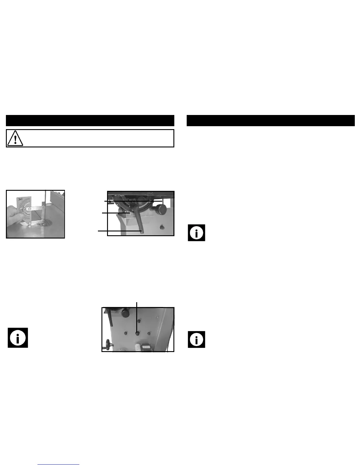
Checking and setting the table angle:
The angle between the blade and the main table of the saw is accurately set at the
factory. However time and use of the band-saw may mean that this angle needs to be
checked and re-set.
• Place a suitable set square (or similar) against the table and the blade.
Caution! Before carrying out any maintenance, ensure that the band-saw is
turned off and that the plug is removed from the mains supply.
• Loosen the table tilt locking handle and adjust the table until it is accurately set
to 90° to the blade.
• If necessary adjust the table stop screw underneath the table.
• Once the angle is accurately set, lock off the tilt locking handle.
• Check that the scale pointer reads 0°.
• If it does not, loosen the screw and set the pointer at 0 and re-tighten the
screw.
Replacing the drive belt:
Scale pointer
Table stop screw
Tilt locking
handle
• Remove the blade (see page 17).
• Release tension from the drive belt (see
page 19).
• Loosen and remove the drive wheel se-
curing nut and washer (located at the
rear of the saw).
Drive wheel securing nut
Note: It may be necessary to tap
the threaded section of the shaft
with a soft faced mallet to remove
the drive wheel.
15
ASSEMBLY INSTRUCTIONS….cont
Ref. No. Description Ref. No. Description
371. Bottom Panel 379. Rear panel
372. Bolt M8 x 16 380. Front beam
373. Washer 8 mm 381. Left side panel
374. Allen bolt M6 x 20 382. Door
375. Door lock 383. Allen bolt M6 x 20
376. Washer 6 mm 384. Nut M8
377. Nut M6 385. Bolt M8 x 50
378. Right side panel 386. Lock nut M6
• Fit the right hand and left hand side panels to the bottom panel and secure with:
⇒ 4 x M8 x 16 bolts.
⇒ 4 x 8 mm washers.
• Fit the rear panel and secure it to the left and right panels with:
⇒ 6 x M8 x 16 bolts.
⇒ 6 x 8 mm washers.
• Fit the upper and lower front beams and secure to the left and right side panels
with:
⇒ 4 x M8 x 16 bolts.
⇒ 4 x 8 mm washers.
Fitting the door lock:
• Insert the M6 x 20 Allen bolt through the hole in the door lock.
• Fit both through the hole on the outside of the right hand panel.
• Secure with the M6 lock nut.
Note: The left and right hand panels are similar; to tell the difference, the
left hand panel has the hinges for the door and the right hand panel has a
hole on the outside where the door lock will fit.
Note: The lock nut should be tightened enough to secure the door lock, but
not so tight that the door lock does not turn.