28
CARE AND MAINTENANCE….cont
Replacing / tensioning the drive belt:
The main drive belt is set at the factory to the correct tension, but time and use may
mean that the belt needs to be re-tensioned.
To re-tension the drive belt:
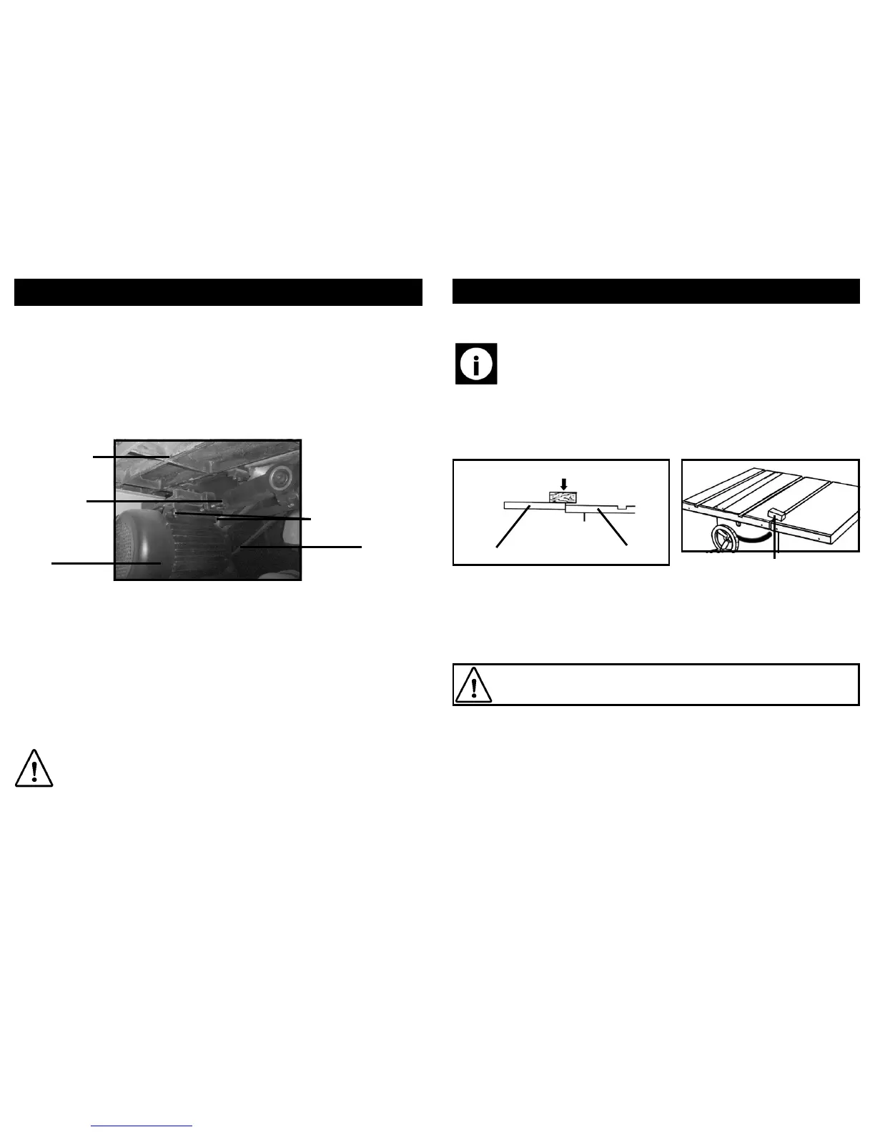
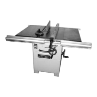
• Open the main side door of the saw and make yourself familiar with the internal
components (see picture below).
Motor
Tension bolt
Motor mount bolts
Main saw bed
Drive belt
• Loosen the 4 x (2 on each side) motor mount bolts.
• Turn the tension bolt whilst checking the tension of the belt.
• Once the correct tension has been achieved (approximately 1”-1
1
/2”) , re-tighten
the motor mount bolts to secure.
To replace the drive belt:
• Release the tension from the belt by following the instructions above.
• Remove the blade (see instructions on page 24).
• The belt can now be removed and replaced.
• Follow all previous instructions in reverse to re-fit the blade, blade guard etc.
Caution: Check for alignment of moving parts, free running of moving parts,
breakage of parts, and any other conditions that may affect its operation Be-
fore restarting the saw.
17
ASSEMBLY INSTRUCTIONS….cont
Scrap piece of wood (if a soft
mallet is not available)
• Sit a straight edge across the extension table, or tables depending on how long
your straight edge is, and across the main saw bed.
• Using the straight edge as a guide, tap the joints between the extension table /
tables and the main saw bed with the mallet or scrap of wood until all tables are
level.
• Tap at the front and the back of the tables to ensure that they are correctly set
in all directions.
Tip: The rip fence (inverted) makes a good straight edge.
Tap here
Main saw bed
Extension table
• Once you are happy that all the tables are correctly set and level proceed to
tighten all the bolts to ensure that the tables stay in place.
Fitting the front fence rail:
Caution! The front and rear rails must be carefully aligned to reduce the
risk of kickback, which can cause serious injury.
• To install the front rail will require the following hardware:
⇒ 5 x square head bolt.
⇒ 5 x 8 mm flat washer.
⇒ 5 x M8 hex nuts.
⇒ Right and left end cap for front rail.
⇒ 6 x self-tapping screw.