18
ASSEMBLY INSTRUCTIONS….cont
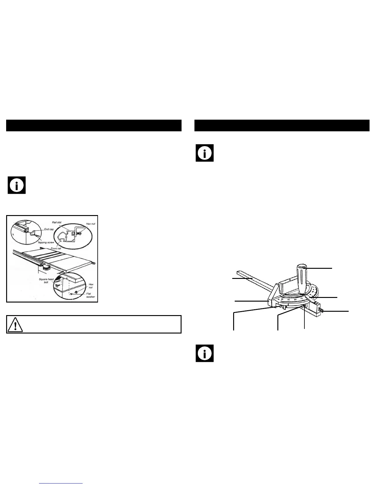
• Insert the 5 square head bolts into the holes on the front of the main table and
extension tables, so the bolt heads extend out 6 mm.
• Loosely attach a flat washer and a hex nut to each bolt.
• Slide the slot on the front fence rail over bolts until the rail is in its correct posi-
tion.
• Adjust each bolt to fit the rail closely to the table.
• Push the rear fence rail against table and hand tighten each hex nut.
Note: Ensure there are no gaps between the rail and the edge of the main
table or extensions.
• Fit the end caps on the rail ends, secure them with the self-tapping screws and
tighten with Phillips screwdriver.
Fitting the rear fence rail:
Caution! The front and rear rails must be carefully aligned to reduce the risk
of kickback, which can cause serious injury.
• To install the rear rail will require the following hardware:
⇒ 5 x square head bolt.
⇒ 5 x 8 mm flat washer.
⇒ 5 x M8 hex nuts.
27
CARE AND MAINTENANCE….cont
• Adjust the distance between the blade and the riving knife (b).
Note: The gap should be between 3 mm and 8 mm.
• Once the gap has been correctly set, re-tighten the nut (a).
• Re-install the table insert and blade guard.
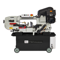
Adjusting the mitre gauge angle:
The mitre gauge has quick set stops at 0° and +/- 45° with the mitre gauge stop pin
and adjustable stop screws. The stop screws are factory set for accuracy but after time
and use, the gauge may need to be re-set, this can be achieved by the following:-
• Loosen the angle lock knob and pull out the stop pin.
• rotate the mitre gauge until the stop pin rests against the 0° stop screw.
• Place a 90° square against the mitre gage rod and the mitre gauge base.
• If the rod is not square, Loosen the lock nut of the 0° stop screw 8 mm wrench.
• Adjust the 0° stop screw until a true 90° angle is achieved.
• Tighten the lock nut to secure, and adjust the angle pointer to read 0°.
• Adjust the plus and minus 45° stop screws using a 45° triangle and the steps
above.
Mitre gauge rod
Angle lock knob
Stop pin
Mitre gauge base
45° stop screw
0° stop screw 0° lock nut
Angle pointer
Note: The mitre gauge provides close accuracy for angled cuts, for very
close tolerances, test cuts are recommended.