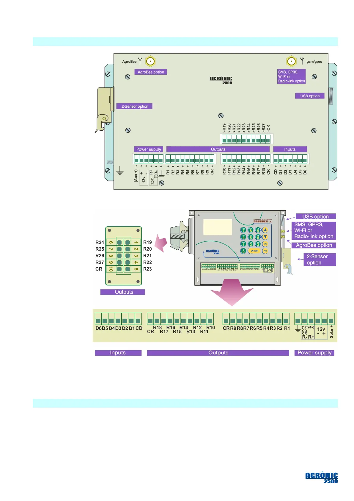
5.2. CONNECTION LOCATIONS
To connect the
“built-in” equipment
model, access the
backside located
inside the desk or
closet. Here we find
the connections for
the power supply,
inputs, and outputs
on the 9-, 18- or 27-
input models.
What’s more, when
more options have
been installed, there
may be connections
for the antennas
used in the AgroBee
option or a PC link
using GSM/GPRS or
radio-link; on the
sides there may be a USB port connection and the option for two analog sensors.
On the “wall-
mount box”, re-
move the bottom
cover to access the
connectors.
To insert ca-
bles, the necessary
holes will have to
be punched out (do
this with the con-
nection cover in
place and screwed
in to avoid breaking
it).
The 27-output
model has the last
nine outputs locat-
ed in a connector
on the left side.
The connect-
ors and antennas
from the rest of the
options are located on the right side.
It is recommended to connect the wires to the terminal using the terminal connectors that come with the
equipment. (The terminals accept cables of up to 2.5 mm
2
in diameter).
5.3. CONNECTIONS
The installation must be performed according to the current regulations applying to electrical installations.
The equipment will not be adequately protected if it is not used in the way that has been specified in this manual.
The unit shall be placed in such a way that the wiring connections of any elements susceptible to interfer-
ence, such as the sensor inputs, sensor power supply, PC links, and power supply intakes, are installed in the
best possible location so as not to receive interference from powered elements which may be nearby.
All the connection terminals on the Agrónic 2500 can be plugged in, which allows for quick maintenance.