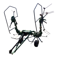
ASSEMBLY STEPS
24
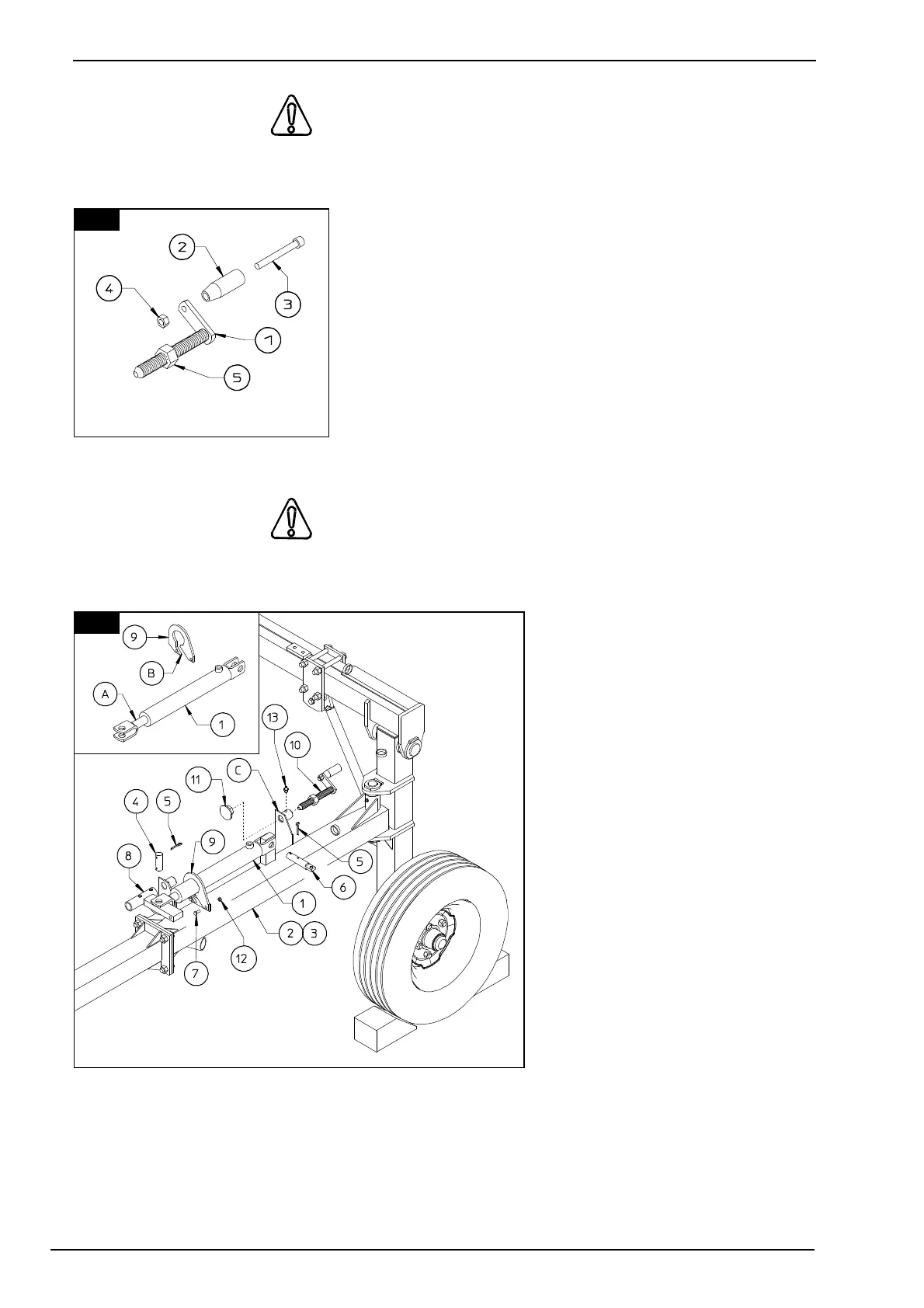
22. DANGER
Insert screw 3 in hand grip 2 and then screw it in the threaded hole in crank 1. Screw 3 should
not be fully tightened, so that hand grip 2 can turn freely.
Lock screw 3 in place with nut 4. Fit nut 5 onto the thread
of crank 1.
In this step, you will use:
Item 3:
2 - knurled-head screws M 12 x 100
(15/32" x 4")
Item 4:
2 - nuts M 12
(15/32")
Item 5:
2 - nuts M 22
(7/8").
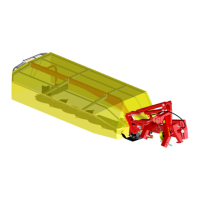
23. CAUTION
Attach cylinder 1 to sections 2 & 3 (LH - RH) and fasten it with pin 6 and split-pins 5. Fit the
cylinder guides 9 to sections 2
& 3 (LH - RH) passing through
point A and slot B. Fasten in
place the cylinder guides 9 to
sections 2 & 3 (LH - RH) with
screws 7 and nuts 12.
Connect attachments 8 to the
forks on the piston end of
cylinders 1, fastening them with
pins 4 and split pins 5. Insert
crank 10 in the correct hole of
bracket C. Then screw the plate
11 to crank 10. Screw the
grease nipple 13 to bracket C.
In this step, you will use:
Item 4:
2 - pins D 25 x 70
(D 1" x 2" 3/4")
Item 5:
4 - split pins D 6 x .35
(D 15/64" x 1" 3/8")
Item 6:
2 - pins D 25 x 132 (D 1" x 5" 3/16)
Item 7:
4 - screws M 8 x 25 (5/16" x 1").
Item 12:
4 - nuts M 8 (D 5/16")
Item 13:
23
22