ASSEMBLY STEPS
9
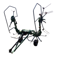
5. Assembly steps
In the steps for assembly we will use the terms "RH part" and "LH part". The distinction is
conventionally made looking at the machine from the rear. For the purpose of simplification, we
will illustrate machine assembly for one side only; since the machine is symmetrical, each
operation must be done on both sides.
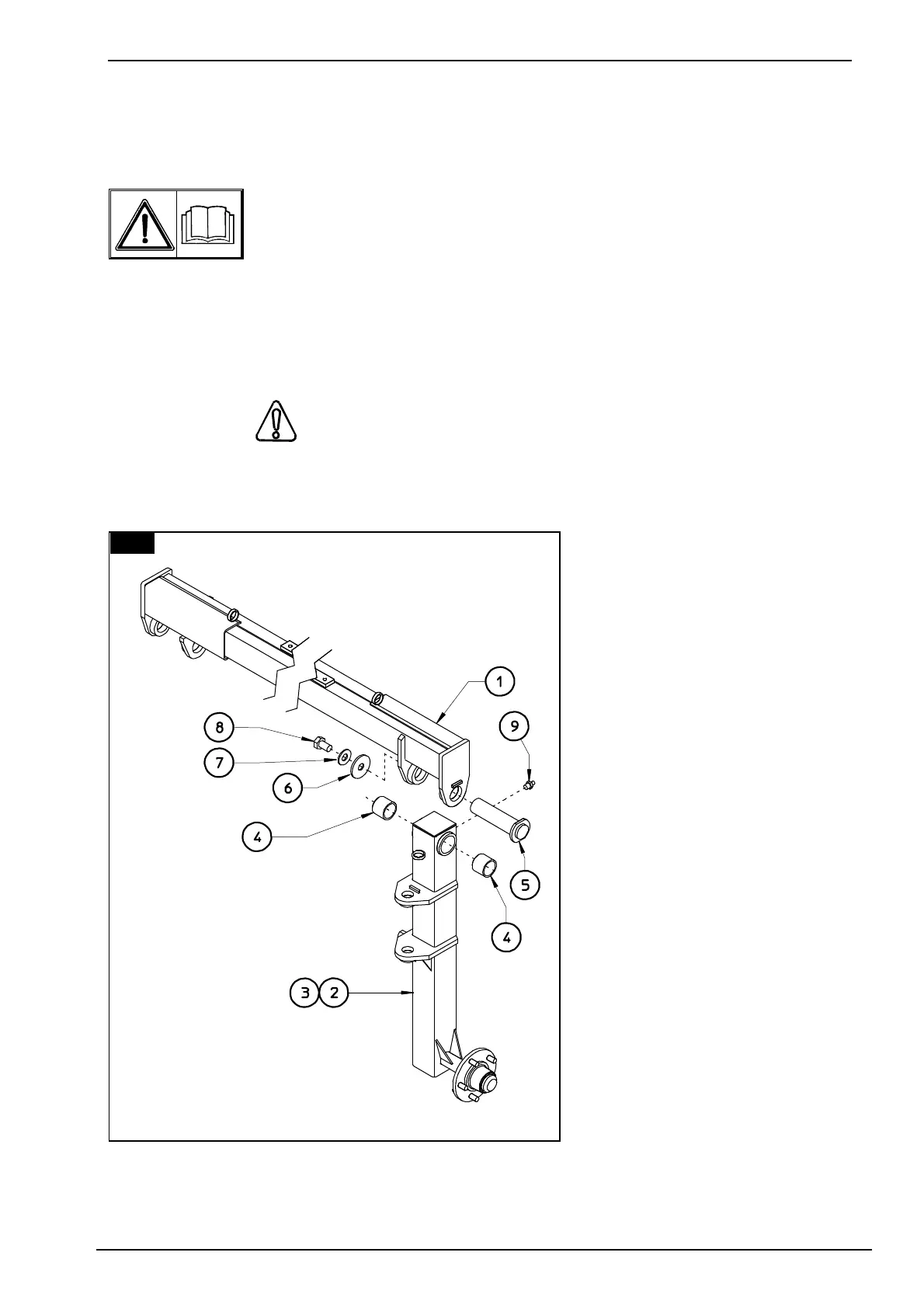
1. ATTENTION
Fit bushings 4 on proper seats of uprights 2 & 3. Attach the wheel supports 2 & 3 (LH - RH) to
the
cross member assembly 1
using pins 5, washers 6 & 7 and
screws 8. To identify parts 2 & 3
(LH - RH) see the next step.
NOTE: measurement labels
(see next figure) must be read
from the rear side of the
machine.
In this step, you will use:
Item 4:
4 - bushings D 50 - 60 x 50
(D 2" - 2" 3/8 x 2")
Item 5:
2 - pins D 50 x 190
(D 2" x 7" 1/2)
Item 6:
2 - washers D 23 - 75 x 12
(D 29/32"- 3" x 1/2)
Item 7:
2 - Grower washers
D 23-35x4
(29/32" - 13/8" x 5/32")
Item 8:
2 - screws M 22 x 50
(7/8" x 2")
Item 9:
2 - grease nipples M 8
(5/16")
1