Do you have a question about the SKF CMPT CTU and is the answer not in the manual?
Details on user-configurable front panel features like switches, indicators, and connectors.
Explains the states and meaning of the SENSOR OK lamp for fault detection.
Details the CAN-bus interface and auxiliary 24V DC power output for external devices.
Covers sensor input types, sensitivity, and environmental operating conditions.
Details physical construction, power requirements, and consumption.
Lists and describes vibration analysis modes and their frequency bandwidths.
Explains vibration and temperature analog output signal scales and formats.
Lists relevant industry certifications and standards for the device.
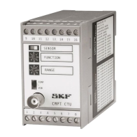
Diagram and explanation of front panel layout, including rotary switches and indicators.
Detailed mapping of terminal pins to specific signals and functions.
Guidelines for safe installation and operation of the CMPT CTU.
Critical warnings regarding voltage, electrical anomalies, and surge protection.
Explains how vibration output scales are derived from sensor and settings.
Details the conversion of temperature readings to analog output signals.
Recommendations for sensor placement, wiring, and environmental considerations.
Wiring diagrams for basic vibration and temperature transmitter setups.
Covers connections for DCL modules and parallel CTU setups.
Guidance for judging vibration levels based on machine classifications and ISO standards.
How to connect the CTU to external dataloggers and vibration analysis systems.
Details on wiring, termination, and setting up multiple CTUs on a CAN-bus.
Explains the CAN message structure, ID format, and protocol layers.
Procedures for identifying CTUs, using services, and managing unit addresses.
How to request and interpret overall measurement values via CAN-bus.
| Supply voltage | 10 - 30 V DC |
|---|---|
| Output signal | 4-20 mA |
| Housing Material | Stainless steel |
| Operating temperature | -40°C to +85°C |
| Storage Temperature Range | -40 to 85 °C |
| Accuracy | ±0, 5 % FS |