19
- switch on/o laser line by pressing switch AD
! before starting a job, check the alignment of the
laser line with the actual line of cut by making a
trial cut on a piece of waste material
• Sawing without slide movement (small workpieces)
- loosen locking knob AH in case it is tightened
- slide the saw head to the stop in the direction of fence
S and retighten locking knob AH
! failure to lock the mechanism can cause the blade
to suddenly climb up on the top of the workpiece
and force itself toward you
- set tool into working position
!
against the saw table and fence S
- switch on the tool by releasing the lock-o AJ and
pulling the main switch AI
! do not cross your arms when operating the saw
head
f
a
- saw through the workpiece with uniform advancing
! the tool should run at full speed before the blade
enters into the workpiece
- switch o the tool by releasing switch AI
- wait until the sawblade has come to a complete
standstill before guiding the saw head slowly upward
• Sawing with slide movement (wide workpieces)
! be aware that the method described below is the
only safe one
- do not pull the saw through the workpiece
- loosen locking knob AH in case it is tightened
!
against the saw table and fence S
- pull the saw head away from fence S far enough so that
the saw blade is in front of the workpiece
g
- switch on the tool by releasing the lock-o
d
and
pulling the main switch
! do not cross your arms when operating the saw
head
f
a
- push the saw head in the direction of fence S and saw
through the workpiece with uniform advancing
g
! the tool should run at full speed before the blade
enters into the workpiece
! if the lower guard does not automatically open
which can happen under certain conditions (e.g.
a workpiece which is very close to the maximum
f
b
- switch o the tool by releasing switch AI
- wait until the sawblade has come to a complete
standstill before guiding the saw head slowly upward
• Sawing grooves
h
- set the desired depth with depth stop AK and lock it in
place by tightening nut AM
- a wooden spacer shall be placed between the
workpiece and the fence for a consistent depth over the
full length of the groove
! ensure that the saw blade does not get jammed in
the workpiece
!
• Changing saw blade
j
! disconnect the plug
- take hex key AN from storage AO
- hold protective guard A in open position
- loosen cover plate screw AQ (do not unscrew the
screw completely)
j
a
- the workpiece clamp has 2 grooves for easy locking;
1 for thin workpieces (up to 5cm) and 1 for larger
workpieces (over 5cm)
- press the workpiece rmly against fence S
- unlock lever R
- adapt clamp to the workpiece
- rmly clamp the workpiece by locking lever R
! for some mitre and bevel combinations, or
depending on the size of the workpiece, it may be
necessary to use commercially available screw
clamps instead of the workpiece clamp
• Setting mitre angles
i
- loosen locking handle AE
- pull mitre detent release lever AF
- rotate the saw table to the left or right and set the
desired mitre angle (from 0° to 50°) by using indicator
AG
- release lever AF
- tighten locking handle AE (do not tighten the handle
)
- for quick and precise setting of often used mitre angles
(0°, 15°, 22.5°, 31.6°, 45°) the mitre detent lever
AF clicks into place at the corresponding positions;
to prevent this, lever AF can be locked in released
position
i
b
• Setting bevel angles
o
- loosen three-legged knob W
- swing the saw head to the left until bevel angle indicator
X points to the desired bevel angle
- adjustable bevel end stop AA (45°) can be used to stop
at 45° or continue until 48°
o
b
- hold the saw head in this position and tighten knob W
- for beveling to the right rst tilt the saw head slightly
to the left, rotate right bevel release knob AB (approx.
60°), then swing the saw head to the desired right bevel
angle
o
c
- when you swing back the saw head to the left the right
bevel release knob AB will automatically reset to 0°
end stop; this can be prevented by rotating the knob to
approx. 90° instead of 60°
o
d
• Compound cuts
p
- compound cuts require both a mitre angle setting and a
bevel angle setting
! do not operate the saw in certain of the mitre
and bevel combinations which may result in
interference between the sliding and stationary
parts of the saw or between the sliding parts and
the workpiece – to make the cut remove sliding
fence, sliding fence lock knob and work clamp
knob as required.
!
• Adjusting the sliding fences
a
- loosen knob V to allow sliding of the fence(s) U
- loosen knob V further to allow removal / assembly of
the fence(s)
- tighten knob V to secure the desired position
! make sure that the sliding fences are secured
! for some mitre and bevel combinations it may also
be necessary to remove the knob
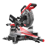
• Laser line
s
- for guiding tool along desired line of cut marked on the
workpiece


 To Next Page